
Let’s see why use Arduino interrupts, including a real example I recently went through. But to start, let’s talk about the delay() function, loved by beginners.
When a person starts with microcontrollers, including Arduino, basic and simple examples are presented. One of these examples is “blink”, which comes with the Arduino IDE.
void loop() {
  digitalWrite(LED_BUILTIN, HIGH);  // turn the LED on (HIGH is the voltage level)
  delay(1000);                      // wait for a second
  digitalWrite(LED_BUILTIN, LOW);   // turn the LED off by making the voltage LOW
  delay(1000);                      // wait for a second
}
Observe the code above, after each “digitalWrite” function a delay(1000) function of 1000 milliseconds is called. The code “stands still”, waiting for the 1000 milliseconds to end. Nothing is executed until this time passes.
One solution is to use the millis() or micros() functions as I explain here. The idea is not complicated: you count a period of time and enter a certain function only after this time has passed. The piece of code below was taken from here.
time = micros();
  if (enterFunction == true){
    previousTime= time;
    Serial.println(previousTime); // for debugging

    // Start your code below
    //-----------------------


    //-----------------------
    // End of your code
  }

  // The DELAY time is adjusted in the constant below >>
  if (time - previousTime < 999990){ // 1 million microsencods= 1 second delay
    /* I have actually used 0.999990 seconds, in a trial to compensate the time that
       this IF function takes to be executed. this is really a point that
       need improvement in my code */
    enterFunction= false;
  }
  else {
    enterFunction= true;
  }
This method works with codes that run fast and at low frequency. I’m going to tell you a case in which I discovered that this function cannot and should not be used for everything.
My experience
At the company where I work, I needed to develop a product where a 55Hz square wave should be generated, in addition to reading digital inputs, reading a keyboard via I2C and controlling a 20×4 LCD display.
I used the code above to perform the four functions (square wave, digital inputs, i2c keyboard, LCD display). My surprise was when I placed the oscilloscope to measure the 55Hz frequency.
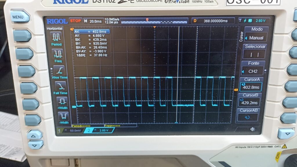
What caught my attention was the fact that the wave was not exactly square, it was a little more similar to a PWM. The frequency remained the same.
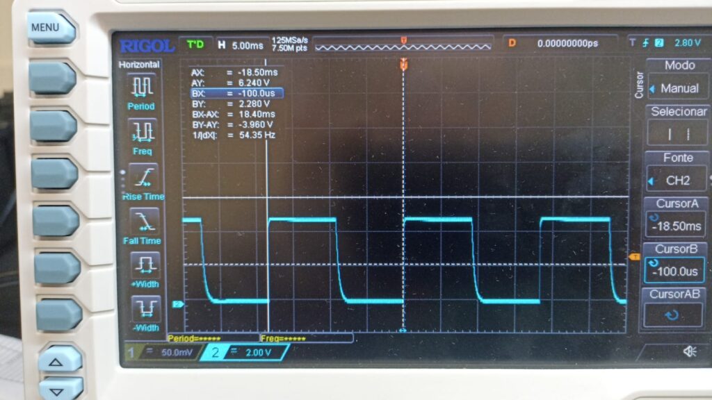
When zooming in a little more, another ungrateful surprise: every second the 55Hz wave was interrupted for several milliseconds.
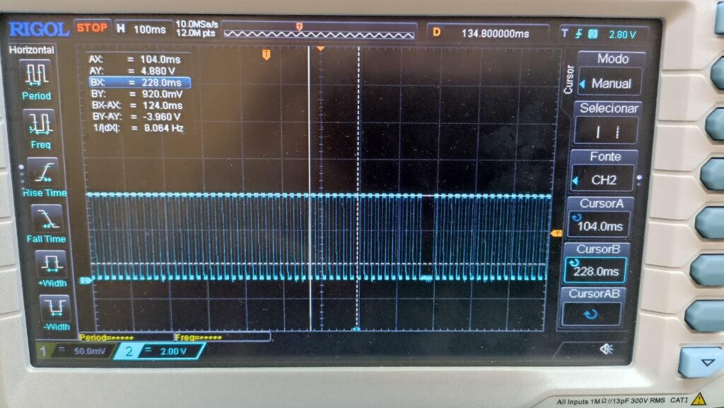
I realized that every second the 20×4 LCD display is updated once. This means that updating the display every second causes the program to “stand still” for several milliseconds.
This is exactly the problem with using micros() or millis() to schedule the program, if any of its functions take longer than the time entered into the function, the program will stop there.
Interrupts then come in, which based on some timer (or even digital inputs) stop the program and take it to where some code needs to be executed. One of the libraries available for Arduino that deals with timer interrupts is timerinterrupt, at this link.
Another way is to use the registers directly, as shown in the example below. Basically in the code below, 55Hz are generated on the pin called “frequency” (pin 21 of the Arduino Mega), by entering the “ISR(TIMER1_COMPA_vect)” function and always changing the output state with “digitalWrite(frequency, !digitalRead(frequency) )”.
 cli();//stop interrupts

  //set timer1 interrupt at 1Hz
  TCCR1A = 0;// set entire TCCR1A register to 0
  TCCR1B = 0;// same for TCCR1B
  TCNT1  = 0;//initialize counter value to 0
  // set compare match register for 1hz increments
  // Frequency was calculated on this site https://www.arduinoslovakia.eu/application/timer-calculator
  OCR1A = 18180; // 110.00495022276003 Hz (16000000/((18180+1)*8))
  // Tive que colocar 110Hz porque cada vez que interrompe é contado um ciclo, porém
  // minha onda quadrada tem nível alto e baixo, dois "momentos" porém em um só ciclo
  // turn on CTC mode
  TCCR1B |= (1 << WGM12);
  // Set CS12 and CS10 bits for 1024 prescaler
  //TCCR1B |= (1 << CS12) | (1 << CS10);
  TCCR1B |= (1 << CS11);
  // enable timer compare interrupt
  TIMSK1 |= (1 << OCIE1A);

  sei();//allow interrupts
}

ISR(TIMER1_COMPA_vect){ //timer1 interrupt 1Hz toggles pin 13 (LED)
//generates pulse wave of frequency 1Hz/2 = 0.5kHz (takes two cycles for full wave- toggle high then toggle low)

  digitalWrite(frequency, !digitalRead(frequency));

}
In the case of the example above, 55Hz is critical, as other functions (i2c, LCD display, keyboard) “can wait”.
To summarize
When we start learning a tool like Arduino, we have no idea what can be done or what not to do. Abandoning delay() is just one step, we then start using functions with micros() and millis().
However, depending on what we want to do and how much code we are going to write, these functions no longer help us, we have to start using “heavy” interrupts. That’s where the game starts to get interesting.