
The 555 integrated circuit is well known in the world of electronics. Let’s now learn how to make a 555 oscillator. Its datasheet lists some of the functions it can do:
- Timer
- pulse generator
- Delay generator
- PWM (pulse width modulation)
- PPM (pulse position modulation)
- Linear ramp generator
The theory of operation of the integrated circuit in this mode (blinker oscillator) is as follows: Capacitor C1 is charged through R1 and R4. When it reaches 2/3 of the circuit’s nominal voltage (66.6%), its discharge begins through R4 to pin 7.
The output (pin 3) is high during charging and low during discharging. the cycle repeats itself. The time calculation is according to the equations below.
t1 (high)= 0.693 * (R1 + R4) * C1
With the values I calculated for the circuit, it turns out:
t1 (high) = 0.693 * (47000 + 47000) * 0.00001 = 0.651 seconds
The time at the bottom (t2) is:
t2 (low) = 0.693 * R4 * C1
Replacing the values the time will be:
t2 (low) = 0.693 * 47000 * 0.00001 = 0.325 seconds
Total time is 0.651 + 0.325 seconds, total 0.976 seconds. The oscillation frequency is therefore F= 1/t(t1+t2) :: F= 1/0.976 = 1.02Hz.
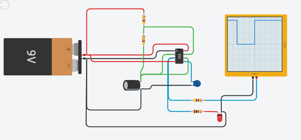
The simulation is at this link and its image is visible below.
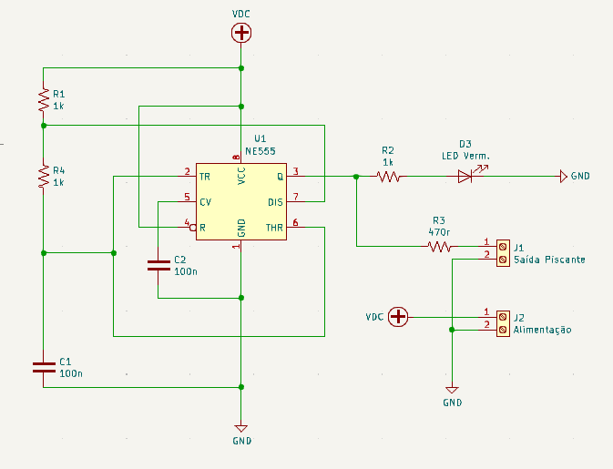
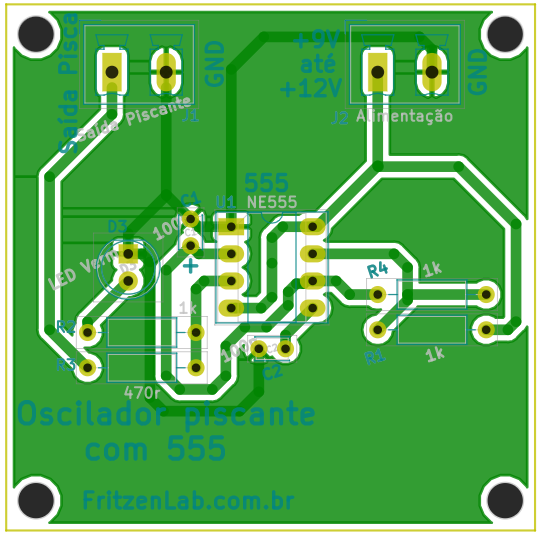
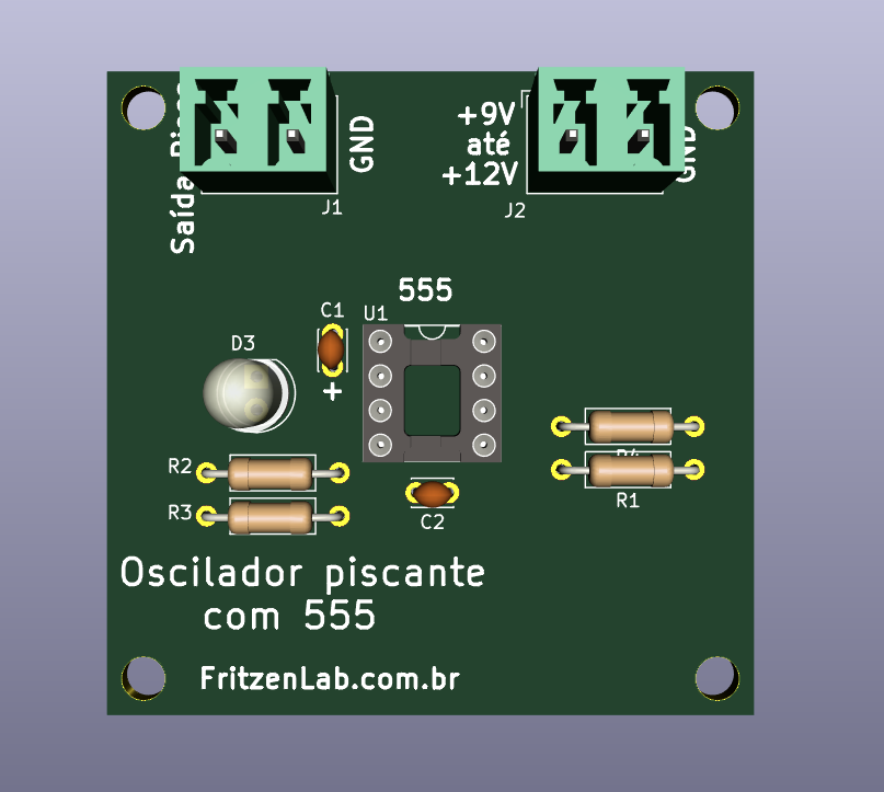
The schematic diagram and printed circuit board are seen below and are available at this link, in Kicad.
This integrated circuit is very versatile, see also timer and PWM generator applications with it. With that in mind, see you in the next articles.