
The 555 integrated circuit is well known in the world of electronics. Let’s now learn how to make an oscillator with 555. Its datasheet lists some of the functions it can do:
- Timer
- pulse generator
- Delay generator
- PWM (pulse width modulation)
- PPM (pulse position modulation)
- Linear ramp generator
PWM stands for “pulse width modulation”. It is widely used to offer a variable voltage, as long as the frequency is filtered by an RC circuit (capacitor resistor).
The theory of operation of the integrated circuit in this mode (PWM generator) is as follows: capacitor C1 begins to be charged through diode D1. When reaching 2/3 (66.6%) of the supply voltage (detected by the THR pin) the capacitor begins to be discharged through the DIS pin and diode D2.
So the cycle starts again. Capacitor C2 is for filtering only. The PWM frequency calculation is as follows (taken from this link).
Load:: t1 = 0.693 * (R1 + RV1) * C1
Discharge:: t2= 0.693 * RV1 * C1
In the case of our example below, the charging and discharging times would look like this (considering a 10k Ohm potentiometer in the middle of the stroke – 5k Ohm for each side).
t1 = 0.693* (1000 + 5000) * 0.0000001 = 415u seconds
t2 = 0.693 * 5000 * 0.0000001 = 346u seconds
The total time would be 415+346 microseconds, therefore 761 microseconds. The PWM frequency would be F = 1 / 0.000761 , F = 1314 Hz (1.314 kHz).
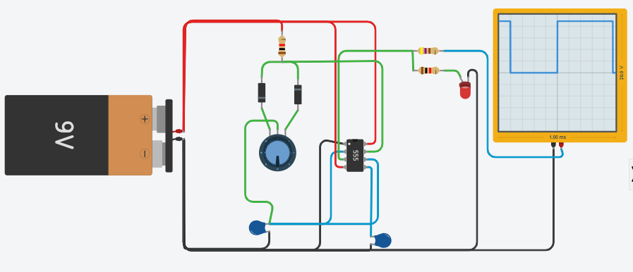
Simulation
The simulation is at this link (TinkerCAD) and below.
The schematic diagram is seen below. Note that there are two diodes, one in each direction, feeding potentiometer RV1. It is these three components that give the difference between time at high level and low level.
During the charge of capacitor C1, diode D1 is conducting, while when discharging C1, it is D2 that conducts. Depending on the position of potentiometer RV1, charging and unloading have different times.
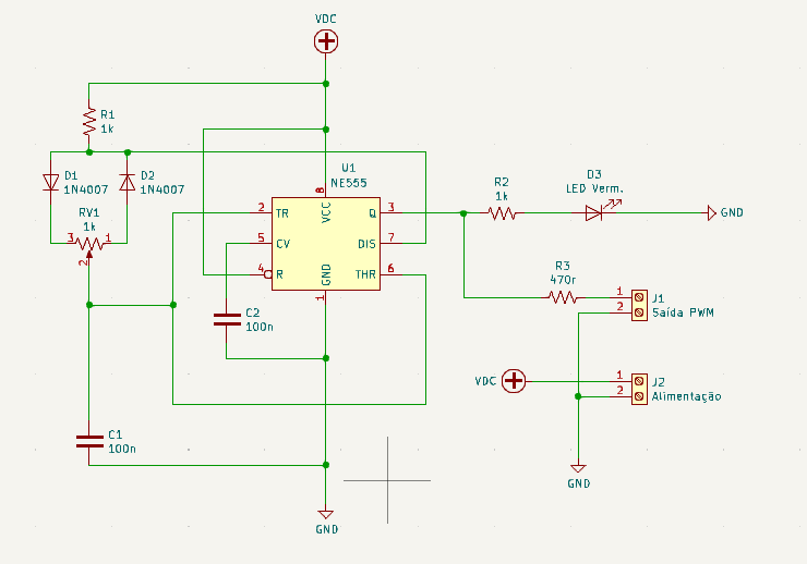
In this circuit, the PWM output can be obtained from connector J1, without the need to remove LED D3 from the circuit. Power is 12V and comes from connector J2.
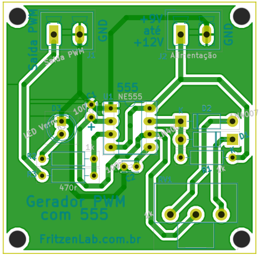
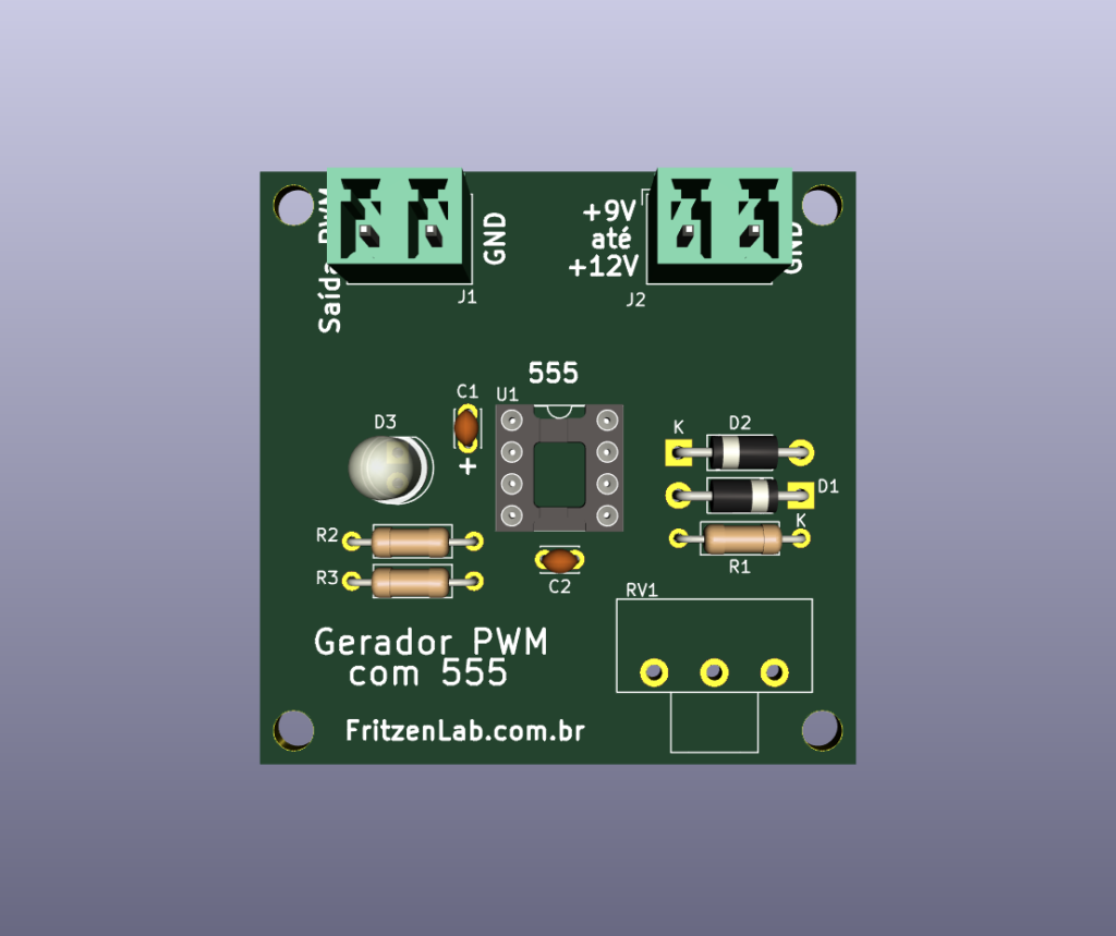
The PCB design (in Kicad) is below, and in this link (all files).
This integrated circuit is very versatile, see also timer and oscillator (blinker) applications with it. With that in mind, see you in the next articles.