
Let’s see how to test thyristor and triac. Thyristor is an electronic component used to control (on/off) loads. It has four PN elements (generally organized in the form PNPN).
The triac in turn is a thyristor capable of conducting current in both directions (the thyristor only conducts from anode to cathode). The thyristor symbol is seen below.
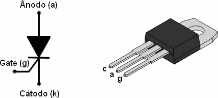
One could understand the thyristor as a diode (semiconductor that conducts current in only one direction) whose on/off control is done by a third pin. One of the major applications of the thyristor is in the dimming of loads (motors, lamps, shower resistors). Dimming means varying the voltage.
The circuit in the video is composed of a 100R resistor on the gate (orange wire), two 100R resistors on the wire and another resistor/LED as a load. When placing the orange wire at +5V the thyristor is activated, when removing it it remains activated. It is necessary to interrupt the load current to turn it off.
In the 70s and 80s, before the appearance and mass distribution of MOSFETs and IGBTs, the thyristor was the main element for controlling power loads. However, its low speed and need for “polarization” made it lose some market share.
Want to dive even more into electronics? look at this experiment I made about reducing relays power consumption.