
Hello readers, today we will learn how to reduce relay power consumption. Relays are electromechanical devices designed to switch (on/off) devices or electrical loads through insulated electrical contacts. More about relays here.
Relays are used in both electronics and electricity (called “contactors”) where “on/off” control of various electrical loads is required, in addition to mechanical and electrical isolation between the control and power circuits.
In the area of electronics and embedded systems, relays are used mainly for the purpose of isolating circuits, as control systems generally operate at low voltage and are very sensitive to external noise.
One of the major problems encountered when using relays is the large current consumption during their operation, as the relay is essentially an inductor (coil) that closes its mechanical contacts through electromagnetic force; to keep its contacts closed (or open, depending on the case) an electric current must be constantly applied to the relay coils; This can kill the viability of an embedded project!
There are several ways to solve the problem of high current consumption in relays, including using a solid state relay (which is essentially a semiconductor), using bistable relays (or “latching relay”, which is basically a relay that maintains its position mechanically, not electrically) or even use an RC circuit in series with the relay coil, as described in this link.
The method
However, I will present to you today a fourth method, which is cheaper than a bistable and solid-state relay and more reliable than a series RC circuit: using PWM modulated voltage, taking advantage of an effect present in each and every inductor, called hysteresis. !.
This method is nothing new, it has even been discussed on the official Arduino forum.
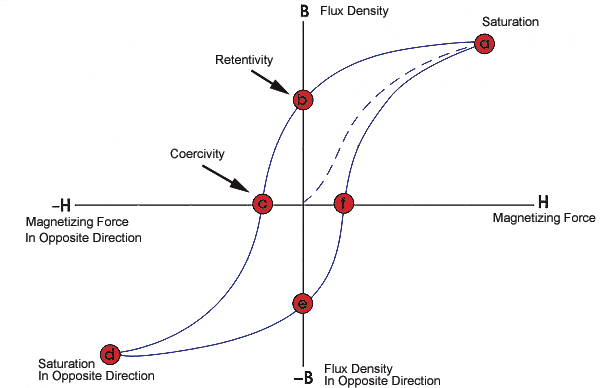
According to Wikipedia, hysteresis is “.. the tendency of a material or system to preserve its properties in the absence of a stimulus that generated them…”; In short, hysteresis allows a coil/inductor, after being magnetized, to remain magnetized even when voltages and currents are applied that are much lower than the “nominal” values of the component.
To exemplify the concept and carry out the tests, I assembled the circuit in the image below:
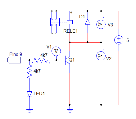
The list of components* used is as follows:
– Q1: NPN bipolar transistor BC548
– Relay1: 5V relay model Srd-05vdc-sc-c
– D1: 1N4007 diode
– 2x 4,700 ohm resistors
– 1x 3mm red LED
The tests
The first test I did was measure the current that the relay consumes when switched on normally (applying 5V to the base of the transistor); the measured current was 66mA, which is very close to the 71.4mA shown in the relay datasheet.
The second test was to apply a PWM signal to the base of the transistor, with the aim of reducing the average voltage applied to the relay. To do this, I used a board compatible with the Arduino UNO to generate the PWM, and the sketch (program) Fading.ino (which comes with the official Arduino IDE) modified to generate the voltage pattern I need:
void loop() { analogWrite(relePin, 255); // turns on the relay, PWM 100% (value 255)
delay(100); // wait 100mS to stabilize the relay
analogWrite(relePin, 130); // lowers the PWM level to 51% (value 130)
delay(3800); // wait 3.8 seconds
analogWrite(relePin, 0); // disconnect from relay, PWM 0% (value 0)
delay(4000); // wait 4 seconds }
Explaining code and results:
1) analogWrite(relePin, 255): firstly, 100% PWM voltage (5V, value 255) is applied to the base of the transistor, as according to its datasheet it is necessary to apply at least 75% of the 5V for the contact to of the relay is closed.
2) delay(100): waiting 0.1 seconds (100mS) for the relay to close. According to the datasheet, this operation should only take 0.01 seconds (10mS).
3) analogWrite(relePin, 130): here comes the great thing about hysteresis, this command reduces the PWM voltage to the value 130, which corresponds to 51% of the relay’s nominal voltage (5V), corresponding to 2.55V. The value of 130 was obtained experimentally, it is one of the lowest values with which I managed to keep the relay on; each relay will possibly need a different PWM value.
4) delay(3800): waits 3.8 seconds with the relay on.
5) analogWrite(relePin, 0): this is the command to turn off the relay, applying the PWM value ‘0’ (0 volts) to the base of the transistor.
Can we reduce relay coil consumption? According to the relay datasheet, the power consumed by the coil when energized is around 0.36W (360mW), a current consumption of 71.4mA at 5V (P= 0.0714 * 5 W).
By lowering the voltage applied to the relay to 51% of 5V (2.55V, as above) the current was reduced to 0.023A (23mA), resulting in a power of P = 2.55 * 0.023 = 0.058W (58mW).
The circuit was left to test for an entire afternoon without losing any activation of the relay, which confirms that this PWM value (51% of 5V) surely works to reduce relay consumption.
Therefore, applying a PWM voltage of 51% of 5V to the relay:
– Relay coil current has been reduced from 66mA to 23mA, a 65% reduction
– Power over the relay coil has been reduced from 360mW to 58mW, an 84% reduction
In summary, if your system needs to have low consumption and you cannot afford or do not want to implement solid state relays, reducing the voltage on the relay coils through PWM can reduce the energy consumption of each relay by 84%.
If you want to know more about other subjects, another really cool project I made is a keypad using just one analog pin to read 10 keys.
Pingback: Real time clock RTC DS1307 Arduino - FritzenLab electronics
Pingback: How to test thyristor and triac - FritzenLab electronics
What I found most valuable is that the technique achieves a significant reduction in relay power consumption while requiring only a microcontroller capable of generating PWM and a simple transistor driver. It shows how understanding the physical behavior of an inductor can lead to practical and low-cost improvements in embedded circuit design.
Relay coils typically require a higher current to activate than to remain energized. By applying full power during activation and then reducing the holding power using PWM, designers can significantly decrease energy consumption without affecting reliable relay operation