
Today you will see something new, at least difficult to find, we will simulate 555 in Arduino. Let’s implement the 555 logic with Arduino code.
Of course this idea is not practical, it doesn’t make sense to use a microcontroller that costs several reais to simulate a chip like the 555, which costs cents. But let’s do it for the challenge, for the beauty of making the code work.
First let’s understand how the 555 works, in this case as an astable (blinker oscillator). We will use the internal schematic diagram of the component (image below), available in its datasheet.
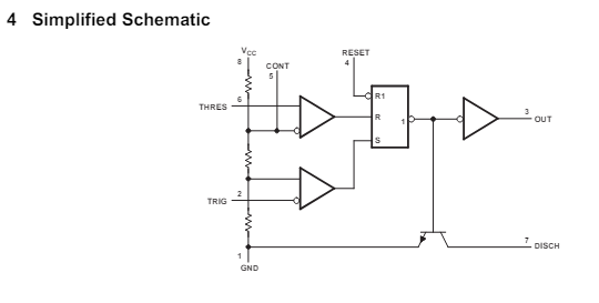
Consider the three resistors in the image to have the same value. So the voltage that will be compared with THRES (threshold) is 66% of the voltage Vcc; with TRIG (trigger) it is 33% of Vcc.
The schematic diagram of a 555 oscillator is seen below and at this link.
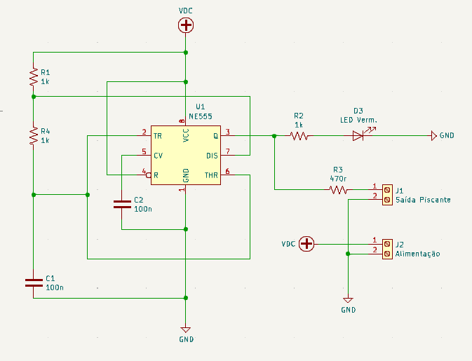
Capacitor C1 is charged through R1 and R4. So when the TRIG (trigger) voltage exceeds 33% of the nominal power supply, the output (pin 3) goes high. When the voltage at THRES (threshold) exceeds 66% of the nominal voltage, pin 3 goes low. The DIS (discharge) pin is activated, starting to discharge the capacitor.
The cycle then restarts, C1 charging begins to occur. I implemented the above circuit in TinkerCAD, below.
The Arduino circuit
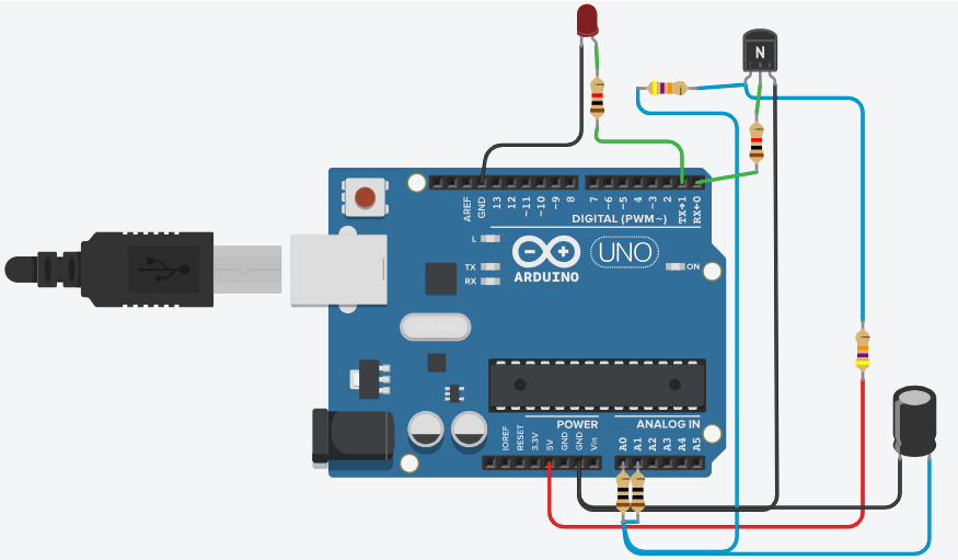
The equation is as below. I used 47k resistors (x2) and a 10uF capacitor. The two 100R resistors on the analog inputs are to avoid shorts due to the charging and discharging of the capacitor.
The transistor is for discharging the capacitor, since pin 0 of the Arduino does not support this discharge alone.
t1 (high)= 0.693 * (R1 + R4) * C1
With the values I calculated for the circuit, it turns out:
t1 (high) = 0.693 * (47000 + 47000) * 0.00001 = 0.651 seconds
The time at the bottom (t2) is:
t2 (low) = 0.693 * R4 * C1
Replacing the values the time will be:
t2 (low) = 0.693 * 47000 * 0.00001 = 0.325 seconds
Total time is 0.651 + 0.325 seconds, total 0.976 seconds. The oscillation frequency is therefore F= 1/t(t1+t2) :: F= 1/0.976 = 1.02Hz.
The code
I didn’t use delay() in this code, as I wanted a fast code. I used a sketch that I invented based on blinkWithoutDelay, in this link.
// Variables used on this code
unsigned long times;
unsigned long previousTime;
boolean enterFunction= true;
//-----------------------

const int trigger_pin2 = A0;
const int output_pin3 = 1;
const int reset_pin4 = 2;
const int threshold_pin6 = A1;
const int discharge_pin7 = 0;
bool dischargeOn = false;


void setup() {
    pinMode(trigger_pin2, INPUT);
    pinMode(output_pin3, OUTPUT);
    pinMode(reset_pin4, INPUT);
    pinMode(threshold_pin6, INPUT);
    pinMode(discharge_pin7, OUTPUT);
}

void loop() {
  times = micros();
  if (enterFunction == true){
    previousTime= times;
    Serial.println(previousTime); // for debugging

    // Start your code below
    //-----------------------


    if(analogRead(trigger_pin2) > 3.333){

        digitalWrite(discharge_pin7, HIGH);
        digitalWrite(output_pin3, LOW);

    } else if(analogRead(trigger_pin2) > 1.666){

        digitalWrite(output_pin3, HIGH);
        digitalWrite(discharge_pin7, LOW);

    } else if(analogRead(trigger_pin2) < 0.2){

        digitalWrite(discharge_pin7, LOW);
      	digitalWrite(output_pin3, LOW);
    }

    //-----------------------
    // End of your code
  }

  // The DELAY time is adjusted in the constant below >>
  if (times - previousTime < 9999){ // 1 million microsencods= 1 second delay
    /* I have actually used 0.999990 seconds, in a trial to compensate the time that
       this IF function takes to be executed. this is really a point that
       need improvement in my code */
    enterFunction= false;
  }
  else {
    enterFunction= true;
  }
}
Basically the code depends on the lines below.
if(analogRead(trigger_pin2) > 3.333){

        digitalWrite(discharge_pin7, HIGH);
        digitalWrite(output_pin3, LOW);

    } else if(analogRead(trigger_pin2) > 1.666){

        digitalWrite(output_pin3, HIGH);
        digitalWrite(discharge_pin7, LOW);

    } else if(analogRead(trigger_pin2) < 0.2){

        digitalWrite(discharge_pin7, LOW);
      	digitalWrite(output_pin3, LOW);
}- I check if the voltage is greater than 3.3V (66.6% of 5V); If so, I turn off the outlet and turn on the flush.
- I then check if the voltage is greater than 1.66V (33.3% of 5V); If so, I turn on the output and turn off the discharge.
- If the comparison voltage is less than 0.2V (discharged capacitor) I turn off the discharge and output to restart the cycle.
Remembering that you can see the simulation working at this link.
Results and discussion
In terms of limitations, the circuit is “run” every 10mS, so it is not possible to obtain blink frequencies of many kHz. Also to use the circuit and code for a timer the code would have to be modified.
Other than that, the experience is interesting, we managed to make an LED blink “simulating” a 555 with Arduino. As future work I want to make a code for a timer (delay).