
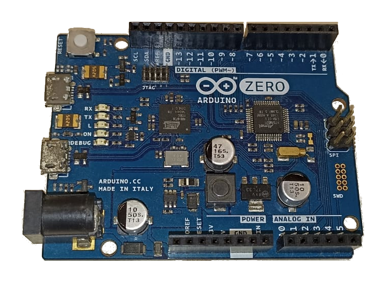
What is Arduino Zero ?. Today I’m going to introduce you to this powerful official Arduino board, which has an ARM Cortex M0+ processor. It was the first of this family to appear on an official Arduino board.
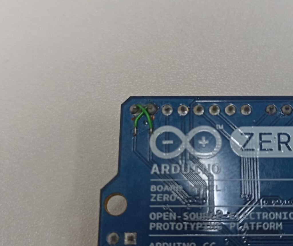
Before it, only the Arduino DUE had an ARM processor (a Cortex-M3). Back in 2014, before the official launch of Zero, I was one of the beta testers, submitted an idea and was selected to win a board to test it out (in the picture below).
It was really a beta test, my board came with jump wires on the serial port of pins 0 and 1. The Arduino Zero is not and has never been very popular, it will never replace the Arduino UNO for example.
This is because it does not have a big difference that justifies its adoption. This is true only on the Arduino platform, because in the “real world” the Cortex M0+ family is widely used due to its low power consumption. They are even direct replacements for the 8bit families.
Technical specifications
In terms of technical specifications, it has a lot of different things from the Arduino UNO. Starting off, it works at 3.3V. If you put 5V it really smokes.
Another interesting point is that it has two USB ports, one connected directly to its main chip (ATSAMD21G18) and another connected to the EDBG chip. This is a second chip on the board that is used for debugging, it is connected directly to the SAMD21 and can even reflash its firmware.
EDBG allows us to program the Arduino Zero also through ATMEL Studio, in addition to the Arduino IDE. Another interesting thing about this board is that it has a 10bit analog output. This means that it can “generate a DC voltage” on pin A0.
Almost all pins (except pin four) can be programmed as an interrupt. It has 256kB of Flash memory, compared to the 32kB of the Arduino UNO. This means more space to store our code.
Despite not having EEPROM memory, it can be emulated in up to 16kB.
What cool projects can you do with it?
According to Arduino’s own website, Zero’s proposal is “to be a platform for innovative projects in IoT, wearables, automation and robotics”.
You can use the low power modes, create an audio frequency meter, test its programming via ATMEL Studio. With the capacity of this board, you can also do a lot of experiments involving core electronics principles, like this one.
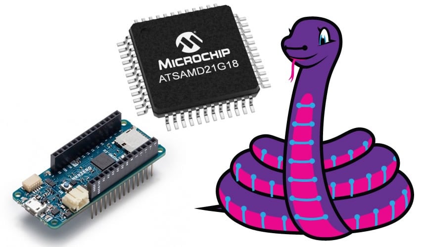
You can even program it in Python, using Adafruit’s circuitPython.
Programming Arduino Zero with the Arduino IDE
First let’s see how to burn the firmware on the ATSAMD21; This step is not necessary, as the plate is already engraved. But I want to show you how it works. Download the most up-to-date Arduino IDE (I downloaded version 2.3.2).
Connect the Arduino Zero via USB DEBUG to the computer. Therefore, it is necessary to download the configuration files for the IDE to recognize the Arduino Zero. Go to “Tools > Board > Board Manager” and type “Zero”. Install the “Arduino SAMD boards by Arduino”.
Now go to “Tools > Board” and select “Arduino Zero programming port”. In “Tools > Programmer” select “Atmel EDBG”. Now click on “Tools > Burn bootloader”.
Blinking an LED with BlinkWithoutDelay
Most sketches that work on the Arduino UNO will work on the Zero, that’s the beauty of the Arduino ecosystem.
Let’s make the famous LED flasher with the BlinkWithoutDelay sketch that comes with the Arduino IDE, in “File > Examples > 02. Digital > BlinkWithoutDelay”.
Here you can either connect the USB cable to the DEBUG port or the native one. I prefer to work on the native USB so there is no risk of messing with the debug chip.
// constants won't change. Used here to set a pin number:
const int ledPin =  LED_BUILTIN;// the number of the LED pin

// Variables will change:
int ledState = LOW;             // ledState used to set the LED

// Generally, you should use "unsigned long" for variables that hold time
// The value will quickly become too large for an int to store
unsigned long previousMillis = 0;        // will store last time LED was updated

// constants won't change:
const long interval = 100;           // interval at which to blink (milliseconds)

void setup() {
  // set the digital pin as output:
  pinMode(ledPin, OUTPUT);
}

void loop() {
  // here is where you'd put code that needs to be running all the time.

  // check to see if it's time to blink the LED; that is, if the difference
  // between the current time and last time you blinked the LED is bigger than
  // the interval at which you want to blink the LED.
  unsigned long currentMillis = millis();

  if (currentMillis - previousMillis >= interval) {
    // save the last time you blinked the LED
    previousMillis = currentMillis;

    // if the LED is off turn it on and vice-versa:
    if (ledState == LOW) {
      ledState = HIGH;
    } else {
      ledState = LOW;
    }

    // set the LED with the ledState of the variable:
    digitalWrite(ledPin, ledState);
  }
}
I set the time to 100ms (0.1s). Note the yellow onboard ‘L’ LED in the gif below.
Testing out the analog output
Another cool feature of the Arduino Zero is an analog output, something the UNO didn’t have. I created a sketch that raises and lowers the voltage value on pin A0. I am connecting an LED to this pin for visualization.
// constants won't change. Used here to set a pin number:
const int ledPin =  LED_BUILTIN;// the number of the LED pin

// Variables will change:
int ledState = LOW;             // ledState used to set the LED
int value = 0;

// Generally, you should use "unsigned long" for variables that hold time
// The value will quickly become too large for an int to store
unsigned long previousMillis = 0;        // will store last time LED was updated

// constants won't change:
const long interval = 50;           // interval at which to blink (milliseconds)

void setup() {
  // set the digital pin as output:
  pinMode(ledPin, OUTPUT);
}

void loop() {
  // here is where you'd put code that needs to be running all the time.

  // check to see if it's time to blink the LED; that is, if the difference
  // between the current time and last time you blinked the LED is bigger than
  // the interval at which you want to blink the LED.
  unsigned long currentMillis = millis();

  if (currentMillis - previousMillis >= interval) {
    // save the last time you blinked the LED
    previousMillis = currentMillis;

    if(value <= 1020){
      value= value + 10;
      analogWrite(A0, value);
    }else{
      value= 0;
    }

    // if the LED is off turn it on and vice-versa:
    if (ledState == LOW) {
      ledState = HIGH;
    } else {
      ledState = LOW;
    }

    // set the LED with the ledState of the variable:
    digitalWrite(ledPin, ledState);
  }
}
The whole secret is in the lines below. Every time I enter the main function (every 50ms) I add 10 to the analog output value, which goes from 0 to 1023.
if(valor <= 1020){
      value= value + 10;
      analogWrite(A0, value);
    }else{
      value= 0;
    }
When passing 1020 I add zero to the variable to start again. Observe the green LED turning on slowly, analogically between 0 and 1020 integers.
What else is important?
Although the Arduino Zero hasn’t caught on much, Adafruit itself has a lot of boards that use the ATSAMD21. You can find a lot of boards based on it on Aliexpress too. And the coolest thing is that it runs microPython, which is great for beginners.
Even with the advent of RISC-V, ARM Cortex still has a long future ahead of it, especially with its low consumption. Arduino itself keeps the ATSAMD21 alive in its MKR line, mainly with the addition of some Wi-Fi and GPS chips.