Hello everyone, everything ok? In today’s article we will learn how to read Arduino digital inputs (buttons, etc.) without interrupting our code for a long time, through external interruption. We will use the attachInterrupt() function.
There are at least three ways to do exactly the same thing (read buttons) using Arduino (and any microcontroller):
- Using the delay() function and literally stopping the program to wait for the button to be pressed,
- Using pseudo-interruptible code through the micros() or millis() functions; I already wrote about this way in this link,
- Through external hardware interrupts.
Of the three ways mentioned above, interruptions are the safest way to control tasks in any system. The program is not stopped and its different parts become independent.
In this article I will implement the attachinterrupt() function, originally available on the official Arduino page. We will use an Arduino UNO, a button and an LED (pin 13 of the Arduino) to demonstrate the concept. The schematic diagram of the experiment is in the image below:
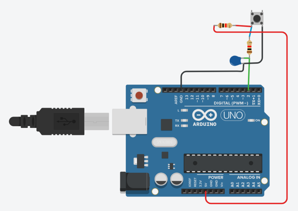
Observe that the key (button) is not alone on the breadboard; This is because I added a series RC circuit, in order to perform the key debounce. I’ve already talked a lot about key debounce in this article, but here’s a quick explanation: no dry contact (key) goes from the “off” to “on” state instantly.
There is always uncertainty for a few thousandths of a second, so if the microcontroller reads the key at this exact moment it can interpret an on as off and vice versa.
The proposed RC circuit serves to delay and stabilize the voltage waveform. Consequently, it allows more certainty in reading the state by the microcontroller.
The code
The code we are going to implement has the function of changing the state of the LED (on or off) each time we press the button on the breadboard. Pressing once turns the LED on and pressing the button again turns the LED off.
Below is the complete code for this test, adapted from the original available on the Arduino website.
// From the official Arduino documentation,
// https://www.arduino.cc/reference/en/language/functions/external-interrupts/attachinterrupt/
//

const byte ledPin = 13;
const byte interruptPin = 2;
volatile byte state = LOW;

void setup() {
  pinMode(ledPin, OUTPUT);
  pinMode(interruptPin, INPUT_PULLUP);
  attachInterrupt(digitalPinToInterrupt(interruptPin), blink, RISING);
}

void loop() {
  digitalWrite(ledPin, state);
}

void blink() {
  state = !state;
}
The code works as follows:
- We used the LED available on pin 13 of the Arduino board and a button (switch) connected to pin 2 (one of the two ports on the Arduino UNO that accepts interrupts).
- The attachInterrupt function is inside the sketch’s setup(), waiting for a change of state in the interruptPin – RISING. That is, when the signal rises from 0 to 5V.
- When detecting this increase in signal (pressing the button) the blink() function is activated; it contains only one state change, state = !state. The previous state is always different from the current one (operator ! in Arduino).
- Inside the program’s loop() there is only the digitalWrite function, which applies the state received in the state variable to the ledPin (pin 13). Therefore, you can execute any other code inside loop(), as the only other thing being executed there is typingWrite().
Below I leave a video testing the code:
See that when you press the button the LED turns on, pressing it again turns it off. It is a simple application, but you can already get an idea of how the function works.


