
Today’s post will be all about temperature sensor comparison. I have picked four different ones to show you how they behave and function. We will learn how to interface them to Arduino UNO and ESP32. Their different applications will be elucidated as well.
At least for me, one of the coolest sensors ever is the temperature one. It is easy to connect, interface and test. Just breathe close to one and see the temperature going up. Or even touch it with your fingers. Or put it on the refrigerator and see the temperature going down in minutes.
I may be the right person to talk about sensor, since I am completely in love with them. I mean, what is cooler than reading the real world and transforming that into electrical signals?. Interfacing sensors (specially temperature ones) with analog and digital circuits is easy: you either have a resistance, a voltage or current, or even a digital signal under a protocol.
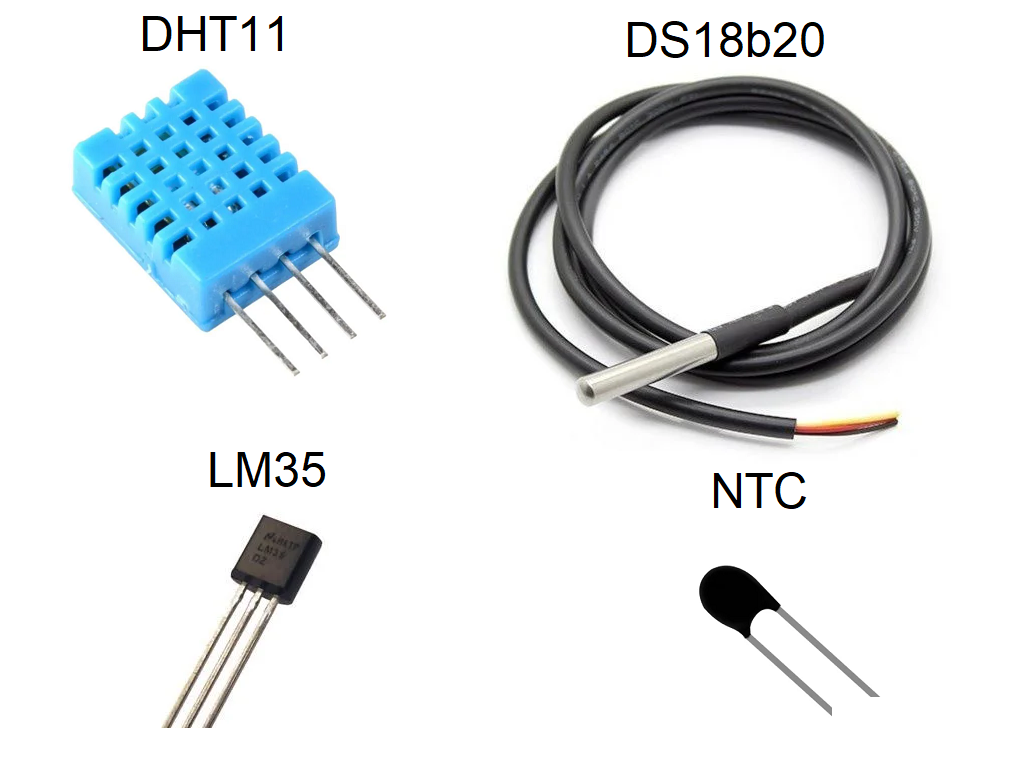
That is the case with the stars of today’s show:
- An NTC (negative temperature coefficient) presents a resistance,
- An LM35 presents a voltage in 10 mV steps,
- Both DHT11 and DS18b20 communicate via a digital protocol, on top of a single wire.
What is this article about?
I am here basically comparing four different temperature sensors. That is useful for when you have to specify a sensor for a project, and do not know where to start from. I will show you the differences, strenghts and weaknesses of each one of them.
We are going to be reading all four sensors at once, in the same room/environment. That will happen every five (5) seconds, already including some filtering. Moving average filter will be applied to all sensor readings, at a rate of 10 seconds for completely new readings. This is since our sensor readings happen every two (2) seconds.
Our medium of choice will be the air, meaning all sensors will be just “hanging around” in free air. LM35 will be on a breadboard and all other three are cable-soldered, so hanging on the bench. I picked just free air since not all our sensors are made for liquid imersion. In this case I mean the DHT11 and LM35. DHT11 is just a no-no since it is all open, featuring only a fragile plastic encase; LM35 has metal (copper) leads that can oxidize. We could totally submerge both DS18b20 and NTC, but not DHT11 and LM35.
Components/sensors limits
Before we dive too much into technicalities, I want to introduce you to our contenders. Three of them are integrared circuits, namely DHT11, DS18b20 and LM35. This means they all feature some sort or extent of manufacturer calibration. Only one of them is truly analog, which is the NTC. It will demand careful equationing to actually convert its resistance and voltage into useful temperature data.
For your future reference, this article will use the SI unit “degrees Celsius (ºC)” for all its technical discussion. Let us start from the DHT11, whose datasheet is here. It also features humidity readings, which we will not use today. It will read temperatures between 0ºC and 50ºC at 8 bit and with 1ºC resolution, roughly every ten (10) seconds. It can be power from 3V to 5.5V; for this experiment I have chosen 3.3V.
LM35 in the other hand is a sensor whose datasheet is here. It will read temperatures between -50ºC and 155ºC at 10 mV/ºC steps. This means that every 1ºC of temperature elevation will see a 10 mV incread in its temperature reading. Its resolution is 0.5ºC, comparatively better than the DHT11. It is specified to work from 4V all the way to 30V. I have read on that internet that it works at 3.3V, so I tested and confirmed it.
Our NTC thermistor is a 3 mm body with a Beta gain of 3950, according to this datasheet. That beta value is super important, since it defines and controls the shape and steepness of its resistance-temperature curve. These sensors can be found with literally hundreds of different configurations. For that reason it is important that, upon buying and NTC thermistor, you always ask for the corresponding datasheet.
I have powered it up with 3.3V for this experiment, since our ESP32-C6 analog inputs work within that range too. This specific part I own is specified to read from -30ºC to 110ºC.
Finally the DS8b20 is a metal-encapsulated integrated circuit, meaning it is like a normal integrated circuit, then covered with a metal tube. Its datasheet specifies its temperature range as being -55ºC to 125ºC, so a little narrower than the LM35 one. It brings an accuracy of 0.5ºC only between -10ºC and 85ºC. It can be powered from 3V all the way to 5.5V; I choose to power it with 5V for this experiment.
Looking into all of their reading range, we can see that they are essentially made for environmental use. It then means that all of them are usable in human-interacting machines and equipment. That is very different from for example thermocouples, that can read up to 1,000+ ºC and up. Or even -100ºC and down. For that reason and also the fact that not all of them are liquid-ready, our experiment will consist on reading room temperatures only.
Temperature sensor hardware
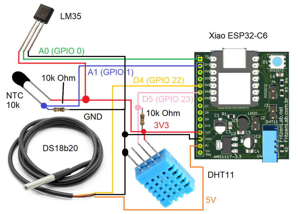
This experiment will require a higher level of attention to detail than the average ones I do here. Three of the sensors feature three wires, two of them feature pull-up resistors. One of the sensors is analog and three are digital. Only one of the four sensors is power with 5V.
This experiment requires a bunch of jumper wires and a great deal of breadboard area, if you choose to use one. For that reason I choose my own ESP32-C6 dev board, which I created specifically to save breadboard space. That way I am able to fit such complex experiments in small-ish 400-points breadboards. Schematic diagram is below, with color code to differentiate sensor circuits.
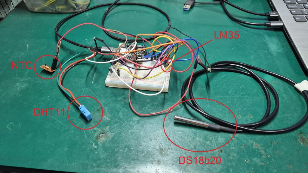
As I told you before, there are a lot of jumper wires to this build. Picture below shows it all, where the LM35 sensor is barely visible on the breadboard. I tried my best to organize it, but reckon I failed that task. What matters is that it actually worked as intended, reading all four temperature sensors.
I recommend you exercise calm and patience while assembling this project. After you are done, just go back wire by wire, connection by connection and double check everything. Be specially careful to check that the only sensor connected to 5V is the DS18b20. All other three are hooked to 3V3. Check pin sequence, mainly on DIP-encapsulated packages like the DHT11 and LM35.
Check that both DHT11 and DS18b20 feature pull-down resistors of 4k7 or 10k Ohm, between signal and 5V (for DS18b20) / 3V3 (for DHT11). I got both voltages from the Xiao ESP32-C6 I am using: it features a pin with 3V3 output and another pin with VBUS output, which is the USB cable voltage.
The code/firmware setup
I am going to be implementing our code in Arduino language, using the software Arduino IDE for that. The version I have installed is v2.3.8 nightly, but you can run others at will (as long it is not older than v1.8.x). You are going to need a couple of libraries to make sensors work, listed below:
- DHT sensor library from Adafruit, for DHT11,
- OneWire by Jim Studt and Tom Pollard, for DS18b20.
- No special library for NTC or LM35, just good old analogRead().
Both libraries are available to find and install from within the Arduino IDE itself. Just go to “Sketch > Include library > Manage Libraries …”. Special mention to the OneWire library I installed, that was the one that worked with my (relatively new in 05/2026) Xiao ESP32-C6 board. At the time you execute this tutorial, and regarding the board you will use, you may have to find another “One Wire” library. That also may include modifying the code provided a bit.
For data visualization I will offer you two ways: first one is the good old Arduino IDE’s serial plotter. I have organized the Serial.print()’s in a way that it is perfect for plotting. All four signals will appear named on screen, along with the chart lines in four distinct colors.
Now I wanted to go a bit further, then decided to create a web page to visualize data. I am no web designer, but I know there is a function/part/plugin in Google Chrome browser to read serial port information. It is called Web serial and it just works, guys. For that part I got help from generative AI, which generated a ready-to-go piece of code with HTML and Javascript. It is inlcuded on the code repository here; more on that later.
Firmware/code for this project
Full Arduino code to make our ESP32-C6 read four different sensors is seen blow. It is also available on my GitHub here. Code explanation will come after this block.
#define LED 15
#define ONE_WIRE_BUS 22 // D4 of Xiao ESP32-C6
#include "OneWireESP32.h"
#include "DHT.h"
#define DHTPIN 23 // D5 of Xiao ESP32-C6
#define DHTTYPE DHT11   // DHT 11

DHT dht(DHTPIN, DHTTYPE);

OneWire32 ds(ONE_WIRE_BUS);
uint64_t ds18b20addr;
bool ds18b20Found = false;

unsigned long ledTimer = 0;
unsigned long sensorsTiming = 0;
unsigned long printTiming = 0;
const int elapsedPrint = 5000;
const int elapsedSensors = 2000;
const int elapsedLed = 300;
bool ledStatus= false;
float LM35 = 0.00;
float NTC = 0.00;
float DHT11read = 0;
float DS18B20 = 0;

// 3950 from here https://www.gotronic.fr/pj2-mf52type-1554.pdf
const double beta = 3950.0;
const double r0 = 10000.0;
const double t0 = 273.0 + 25.0;
const double rx = r0 * exp(-beta/t0);
const double vcc = 3.43;
const double R = 9830.0; // measured it 05/24/2026
float smoothDHT11;
float smoothDS18B20;
float smoothNTC;
float smoothLM35;
uint8_t devices= 0;

class MovingAverage {
  private:
    int _numReadings;
    float *_readings;
    int _readIndex = 0;
    float _total = 0.0;

  public:
    MovingAverage(int size) {
      _numReadings = size;
      _readings = new float[_numReadings];
      for (int i = 0; i < _numReadings; i++) _readings[i] = 0.0;
    }

    ~MovingAverage() {  // free memory
      delete[] _readings;
    }

    float update(float newValue) {
      _total -= _readings[_readIndex];
      _readings[_readIndex] = newValue;
      _total += newValue;

      _readIndex++;
      if (_readIndex >= _numReadings) _readIndex = 0;

      return _total / (float)_numReadings;
    }
};

void blinkLED(){
  if(millis() - ledTimer > elapsedLed){
    ledTimer += elapsedLed;
    if(ledStatus == false){
      ledStatus= true;
      digitalWrite(LED, HIGH);
    }else{
      ledStatus= false;
      digitalWrite(LED, LOW);
    }
  }
}
float readLM35(void){
  float total = 0;
  int samples = 20;

  for(int i = 0; i < samples; i++){
    // 1. Force a read on A1 first to intentionally exhaust any trapped
    // cross-channel voltage coupling between A1 and A0
    analogReadMilliVolts(A1);
    delayMicroseconds(200);

    // 2. Perform two dummy reads on A0 to let the ADC's internal
    // sampling capacitor fully stabilize to the LM35's actual voltage
    analogReadMilliVolts(A0);
    delayMicroseconds(100);
    analogReadMilliVolts(A0);
    delayMicroseconds(100);

    // 3. Now collect the true, unpolluted sample
    total += analogReadMilliVolts(A0);
    delay(5);
  }

  long mv = total / (float)samples;
  return mv / 10.00; // LM35 = 10mV per degree C
}
float readNTC(void){
  delayMicroseconds(50);
  float v = analogReadMilliVolts(A1) / 1000.0;
  float rt = (vcc * R) / v - R;
  float tempK = 1.0 / (
    (1.0 / t0) + (1.0 / beta) * log(rt / r0)
  );
  float tempC = tempK - 273.15;
  float ntcrawfinal = tempC;
  return ntcrawfinal;
}
float readDS18B20(){

  if(!ds18b20Found){
    devices = ds.search(&ds18b20addr, 1);
    return 0;
  }
  float temp;
  ds.request();
  delay(100);
  uint8_t err = ds.getTemp(ds18b20addr, temp);
  if(err){
    return 0;
  }else{
    if(temp > -20 && temp < 80){
      return temp;
    }else{
      return 0;
    }
  }

}
float readDHT11(){
  float dht11raw =  dht.readTemperature();

  if (isnan(dht11raw)) {
    dht.begin();
    return 0;
  }else{
    return dht11raw;
  }
}
// do a moving average filter
MovingAverage tempDHT(5);
MovingAverage tempDS(5);
MovingAverage tempNTC(5);
MovingAverage tempLM(5);
void setup() {

  // put your setup code here, to run once:
  analogReadResolution(12);
  analogSetPinAttenuation(A0, ADC_11db);   // LM35
  analogSetPinAttenuation(A1, ADC_11db);  // NTC
  pinMode(LED, OUTPUT);
  dht.begin();
  Serial.begin(115200);
  devices = ds.search(&ds18b20addr, 1);
  Serial.print("Devices found: ");
  Serial.println(devices);
  if(devices > 0){
    ds18b20Found = true;
    Serial.print("DS18B20 found: 0x");
    Serial.println((unsigned long long)ds18b20addr, HEX);
  }else{
    Serial.println("No DS18B20 found");
  }
}

void loop() {
  // put your main code here, to run repeatedly:
  blinkLED(); // blink the LED for fun

  if(millis() - sensorsTiming > elapsedSensors){ // read DHT11
    sensorsTiming += elapsedSensors;
    LM35= readLM35();
    NTC= readNTC();
    DS18B20 = readDS18B20();
    smoothLM35= tempLM.update(LM35);
    smoothNTC= tempNTC.update(NTC);
    smoothDS18B20= tempDS.update(DS18B20);

    DHT11read = readDHT11();
    smoothDHT11= tempDHT.update(DHT11read);
  }
  if(millis() - printTiming > elapsedPrint){ // read DHT11
    printTiming += elapsedPrint;

    char buf[80];
    snprintf(buf, sizeof(buf), "LM35:%.2f,NTC:%.2f,DS18B20:%.2f,DHT11:%.2f",
     smoothLM35, smoothNTC, smoothDS18B20, smoothDHT11);
    Serial.println(buf);
  }
}
Whole code is non-blocking, meaning it does not get “stuck” in any part waiting for something to happen. There are of course a couple of 100 us and 5 ms blocking delays for reading stabilization. But in the great scheme of things, waiting for 100 us or even 5 ms is practically nothing.
An LED on pin 15 blinks (full cycle) every 600 ms, meaning a 1.66 Hz frequency. That is just for fun and games, that LED does nothing important for us today. LM35 sensor is specially prone to noise, so I have implemented a 20 readings averaging every time it has to be read:
float readLM35(void){
  float total = 0;
  int samples = 20;

  for(int i = 0; i < samples; i++){
    // 1. Force a read on A1 first to intentionally exhaust any trapped
    // cross-channel voltage coupling between A1 and A0
    analogReadMilliVolts(A1);
    delayMicroseconds(200);

    // 2. Perform two dummy reads on A0 to let the ADC's internal
    // sampling capacitor fully stabilize to the LM35's actual voltage
    analogReadMilliVolts(A0);
    delayMicroseconds(100);
    analogReadMilliVolts(A0);
    delayMicroseconds(100);

    // 3. Now collect the true, unpolluted sample
    total += analogReadMilliVolts(A0);
    delay(5);
  }
Our NTC thermistor is a non-linear component, meaning its resistance to temperature ratio is not a straight line. For that reason we have to apply so equationing to every one voltage we read from it:
float readNTC(void){
  delayMicroseconds(50);
  float v = analogReadMilliVolts(A1) / 1000.0;
  float rt = (vcc * R) / v - R;
  float tempK = 1.0 / (
    (1.0 / t0) + (1.0 / beta) * log(rt / r0)
  );
  float tempC = tempK - 273.15;
  float ntcrawfinal = tempC;
  return ntcrawfinal;
}
Our DS18b20 has two small details that we have to observe and execute: new readings take a couple of miliseconds to happen, so we wait for 100 ms before moving forward. Also we want to discard any readings below -20ºC and above 80ºC:
float readDS18B20(){

  if(!ds18b20Found){
    devices = ds.search(&ds18b20addr, 1);
    return 0;
  }
  float temp;
  ds.request();
  delay(100);
  uint8_t err = ds.getTemp(ds18b20addr, temp);
  if(err){
    return 0;
  }else{
    if(temp > -20 && temp < 80){
      return temp;
    }else{
      return 0;
    }
  }

}
Finally for the DHT11 we enter the function already making a reading. It that does not work we try to connect to it again. So that it is already connected the next time we arrive for a reading:
float readDHT11(){
  float dht11raw =  dht.readTemperature();

  if (isnan(dht11raw)) {
    dht.begin();
    return 0;
  }else{
    return dht11raw;
  }
}
Finally we do a moving average filter with five (5) readings, saving the averaged values on variables called “smoothXXXX”. Notice below that we first execute a normal reading of every sensor, as in “LM35= readLM35();”. Only then we call the averaging function by going “smoothLM35= tempLM.update(LM35);”:
    LM35= readLM35();
    NTC= readNTC();
    DS18B20 = readDS18B20();
    smoothLM35= tempLM.update(LM35);
    smoothNTC= tempNTC.update(NTC);
    smoothDS18B20= tempDS.update(DS18B20);

    DHT11read = readDHT11();
    smoothDHT11= tempDHT.update(DHT11read);
Other important details
Serial port printing happens every five (5) seconds, using the function below. It essentially uses the “snprintf” function, that concatenates text and variables into a single char array of (in this case) 80 bytes. My generative AI of choice told me this is very memory-safe.
    char buf[80];
    snprintf(buf, sizeof(buf), "LM35:%.2f,NTC:%.2f,DS18B20:%.2f,DHT11:%.2f",
     smoothLM35, smoothNTC, smoothDS18B20, smoothDHT11);
    Serial.println(buf);
Finally the last detail I have to talk to you about is the analog inputs configuration, which do exist in ESP32. I have decided to read values in 12 bit, meaning I would have 0-4095 integers as answers from LM35 and NTC. That is configured here on setup():
analogReadResolution(12);Another important parameter is the input attenuation, that essentially defines how “high” in voltage your readings can go. I have decided to got 11db for both inputs, meaning I can read values up to 3.9V. Necessary? Yes for the NTC which reads around 2.5V at 25ºC, But not for the LM35, for that I could use for example 6db that would allow me voltages up to 1.75V.
This is since for a higher temperature of 40ºC our LM35 would deliver around only 0.4V. Also add those to setup():
  analogSetPinAttenuation(A0, ADC_11db);   // LM35
  analogSetPinAttenuation(A1, ADC_11db);  // NTC
These ADC (analog to digital converter) configurations highlight the higher complexity which surronds the ESP32. Arduino board were essentially stripped from that, but ESP32 is hightly configurable on that side.
Running the experiment
Copy the full code from above, paste it into your Arduino IDE. Connect your ESP32-C6 board to your computer via USB cable, then select the right board in the top center menu of the IDE. Finally click “Upload”, the “->” arrow to the right on the top left of the IDE.
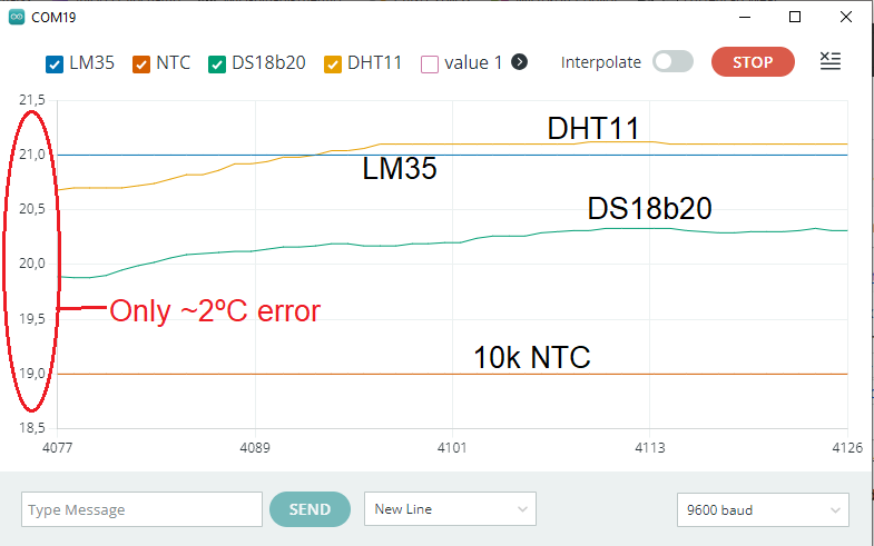
Wait a few seconds for the compilation and flashing to happen, specially since we are using a couple of libraries. That makes the compilation take extra steps, which is normal. After a while you can open the serial plotter screen, by doing “Tools > Serial plotter”. Hopefully you will see something similar to the screenshot below.
Now, remember the WEB serial thing I told you about above? let us test it. Please close the serial plotter and the Arduino IDE completely. It has to be closed, otherwise the Web Serial does not work. Copy the whole HTML code from here and paste it into any text editor (Visual Studion, Notepad, etc). Save it as “SomeName.html”.
Now navigate to the place where you saved the file, right click it and go “Open with > Google Chrome”. In the web page that opens, on the top right you click “Connect”. Every five seconds a new value will appear to all four sensors, as seen in the screenshot below.
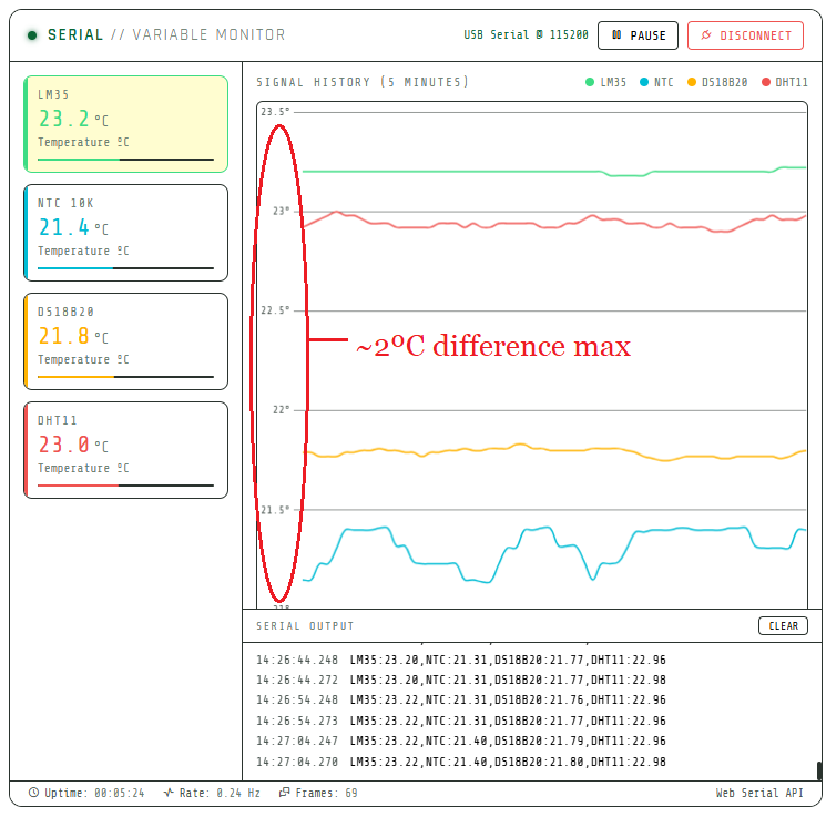
Both ways (Serial plotter or Web serial) have the same outcome, a line graph being generated live for each sensor. I have configured (ok, generative AI has configured) the Web serial application to show 60 data points for each channel on screen. That is one point each channel every five (5) seconds, twelve (12) points each channel for minute. So you can see five (5) minutes of data on your screen at any moment.
Please watch the video I made for this experiment, so you understand it better. It is located at the top of this article, after the first paragraph. Also if you want to acquire the materials used here today, please find below my Aliexpress links:
Data analysis
All these four sensors were connected and used without any previous calibration. It means I am reading them in the state they came from factory. There are also no gains applied to them on my code. So what you are seeing are raw readings, just averaged for eliminating outliers.
Both screenshots above (Serial plotter and Web serial) show the same trend:
- NTC thermistor has the lowest readings. That can vary with a bunch of things, like supply voltage and Beta.
- DS18b20 and DHT11 readings are more stable and in the middle. This may happen since both feature internal integrated controllers, which could (an do) apply filtering.
- The LM35 sensor outputs the highest values of all four. This *could* be due to its encapsulation/case trapping self-heat.
The way both graphs are plotted is a bit deceiving, since we are not seeing for example a 0 to 40ºC scale. What we are seeing in the serial plotter is a 18.5 to 21.5ºC range and on the Web serial is 21 to 23.5ºC range. In reality the difference between the lowest value (NTC) and highest (LM35) is around 2ºC at all times in both representations.
That is exactly what is indicated in one of the screenshots. Such low temperature difference between four uncalibrated sensors is within what is expected, really. Specially if you consider you are doing all this in a home setup, full of uncertainties and sources of random noise. So then comes the questions: which sensor is better?.
To me there is no single answer to that question. Every one of LM35, NTC, DS18b20 and DHT11 has its higher and lower points, which I will list below. Besides that, please feel free to comment below or on the Youtube video, I will make my best to answer you timely.
- NTC thermistor is the cheapest but requires executing math for usable precision. Also some models have an extended reading range, going well above and well below all other options,
- LM35 is also cheap but could be susceptible to noise and self-heating,
- DHT11 features humidity readings but neither that nor temperature readings come with great resolution. Not to mention low update speed,
- DS18b20 is a much better silicon (more precision) than LM35 and DHT11, but that comes with a price. Also worth mentioning the lower reading speed when compared to NTC and LM35.