After bringing you the Franzininho C0 by Fabio Souza and Embarcados portal, today we will be talking about the Franzininho Wi-Fi, an ESP32-S2 based educational development board.
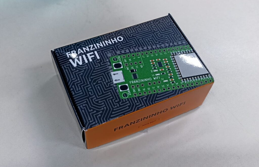
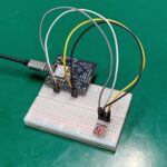
As you can see above it comes in a neat little box, inside of which there is an anti-static bag with the board. The board is based on the ESP32-S chip from Espressif, featuring 2.4Ghz Wi-Fi.
I have been away from embedded systems for some years now, having only programmed the ESP-12 and ESP8266. Let’s see how I go with this little board. By the way, it can be programmed in a variety of ways: Arduino IDE, ESP-idf, CircuitPython, microPython. See the official documentation (Google translate required).
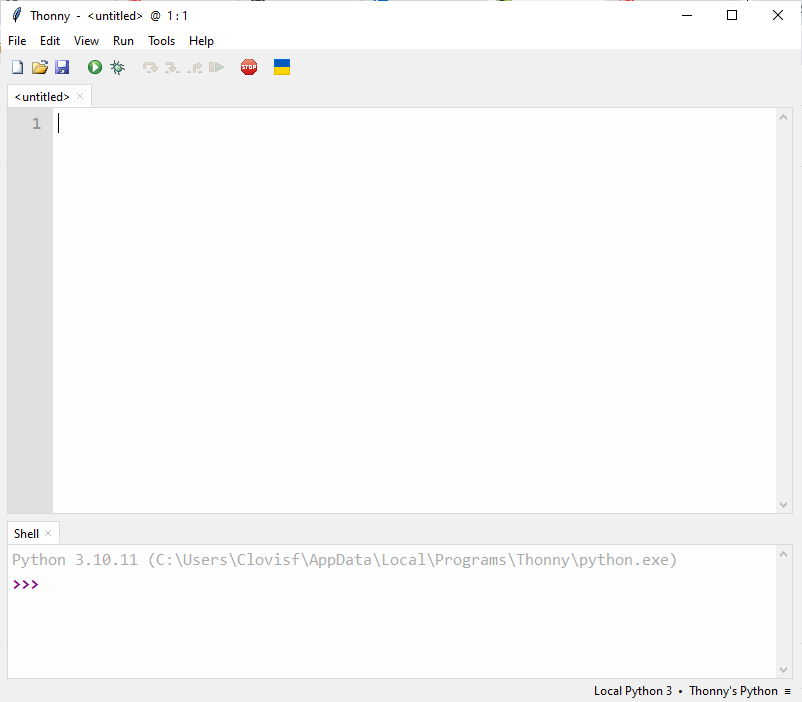
I have decided to getting started with this board in microPython; the documentation available to it is complete, can’t complain (see it here). To begin with, you have to flash microPython into it, following this official guide or this one (which I followed).
The .bin file for the latter can be found here; You have to also download Thonny IDE from here. Important detail: I was not able to make it work with the official way of flashing the bootloader, had to follow the RandomNerdTutorials way, above.
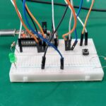
By reading this link, this one and also this one I was able to come up with the code below, that blinks both Franzininho Wi-Fi’s LEDs.
from machine import Pin
from time import sleep

led = Pin(33, Pin.OUT)
led2 = Pin(21, Pin.OUT)

while True:
  led.value(not led.value())
  led2.value(not led2.value())
  sleep(0.5)
Then I made a GIF of the yellow and blue LEDs blinking:
What about Wi-Fi, how to connect it to the internet?
We will implement this code that implements the control of two LEDs on the board via a WEB page. Download the code below to your board and an IP address wil show in the Thonny IDE console. Enter such IP in a WEB browser.
from machine import Pin
import network
import socket
import time
# Define GPIO pins
GPIO1 = Pin(21, Pin.OUT)
GPIO2 = Pin(33, Pin.OUT)
# Initialize GPIO states
GPIO1.value(0) # OFF
GPIO2.value(0) # OFF
GPIO1_state = "GPIO 1 is OFF"
GPIO2_state = "GPIO 2 is OFF"
#WiFi credentials
ssid = 'YOURSSID'
password = 'YOURPASS'
wlan = network.WLAN(network.STA_IF)
#function to connect to Wi-Fi network
def cnctWifi():
wlan.active(True)
print('Attempting to connect to the network...')
wlan.connect(ssid, password)
max_wait = 10
while max_wait > 0 and not wlan.isconnected():
max_wait -= 1
print('waiting for connection...')
time.sleep(1)
# Manage connection errors
if not wlan.isconnected():
print('Network Connection has failed')
else:
print('Connected to the network successfully.')
status = wlan.ifconfig()
print( 'Enter this address in browser = ' + status[0] )
#HTML + CSS for webpage
html = """<!DOCTYPE html>
<html lang="en">
<head>
<meta charset="UTF-8">
<meta name="viewport" content="width=device-width, initial-scale=1">
<title>MicroPython Web Server</title>
<style>
html {
font-family: Arial;
display: inline-block;
margin: 0px auto;
text-align: center;
}
h1 {
font-family: Arial;
color: #2551cc;
}
.button1,
.button2 {
-webkit-border-radius: 10;
-moz-border-radius: 10;
border-radius: 10px;
font-family: Arial;
color: #ffffff;
font-size: 30px;
padding: 10px 20px 10px 20px;
text-decoration: none;
display: inline-block;
margin: 5px;
}
.button1 {
background: #339966;
}
.button2 {
background: #993300;
}
</style>
</head>
<body>
<h1>MicroPython Web Server</h1>
<p>%s</p>
<p>
<a href="/GPIO1/on"><button class="button1">GPIO 1 ON</button></a>
<a href="/GPIO1/off"><button class="button2">GPIO 1 OFF</button></a>
</p>
<p>%s</p>
<p>
<a href="/GPIO2/on"><button class="button1">GPIO 2 ON</button></a>
<a href="/GPIO2/off"><button class="button2">GPIO 2 OFF</button></a>
</p>
</body>
</html>
"""
# Connect to Wi-Fi
cnctWifi()
# Set up socket for web server
addr = socket.getaddrinfo('0.0.0.0', 80)[0][-1]
s = socket.socket()
s.setblocking(0)
s.bind(addr)
s.listen(1)
print('listening on', addr)
# Main loop for handling client requests
while True:
if not wlan.isconnected():
print("Connection failed. Trying to reconnect")
wlan.disconnect()
cnctWifi()
if wlan.isconnected():
try:
cl, addr = s.accept()
print('client connected from', addr)
request = cl.recv(1024)
print(request)
request = str(request)
GPIO1_on = request.find('/GPIO1/on')
GPIO1_off = request.find('/GPIO1/off')
GPIO2_on = request.find('/GPIO2/on')
GPIO2_off = request.find('/GPIO2/off')
if GPIO1_on == 6:
print("GPIO 1 is on")
GPIO1.value(1)
GPIO1_state = "GPIO 1 is ON"
if GPIO1_off == 6:
print("GPIO 1 is off")
GPIO1.value(0)
GPIO1_state = "GPIO 1 is OFF"
if GPIO2_on == 6:
print("GPIO 2 is on")
GPIO2.value(1)
GPIO2_state = "GPIO 2 is ON"
if GPIO2_off == 6:
print("GPIO 2 is off")
GPIO2.value(0)
GPIO2_state = "GPIO 2 is OFF"
response = html % (GPIO1_state, GPIO2_state)
cl.send('HTTP/1.0 200 OK\r\nContent-type: text/html\r\n\r\n')
cl.send(response)
cl.close()
except:
pass
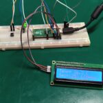
time.sleep(0.1)Enter your Wi-Fi data in YOURSSID and YOURPASS. Pay attention to use the right GPIO in the code; in the case of the Franzininho Wi-Fi board are the 21 and 33 pins. The webpage is as seen below:
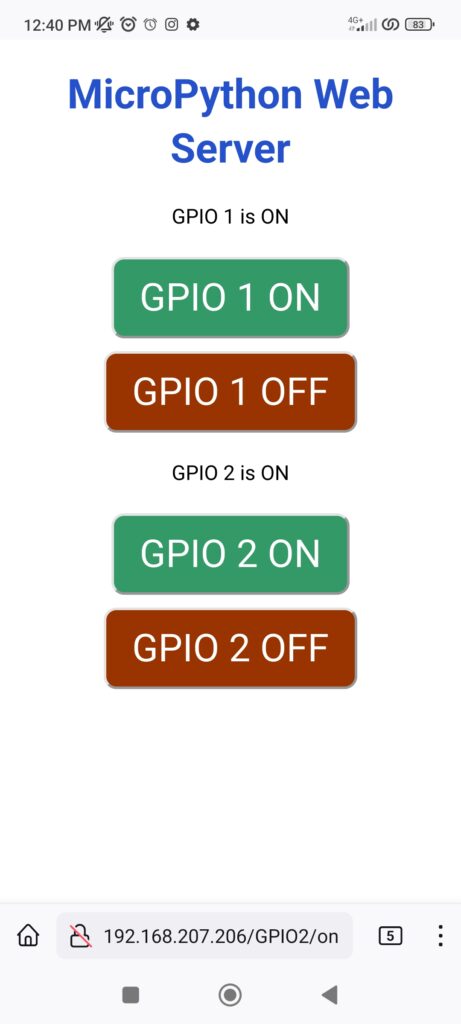
Click “GPIO 1 ON” or “GPIO 2 ON” to turn the LEDs on, and OFF to turn them off; now you shoul look at the board itself.
That’s all for today folks, in a near future you will see more on this board, programmed via Arduino IDE and also ESP-idf.


Leave a Reply