This is the official product page for FritzenLab’s ESP32-C6 dev board. Here you can find all the information about how to use this board, including pinouts, limits, libraries, where to buy it, etc. This board was designed to be a development tool for WiFi products, based on the brand new (2024) ESP32-C6 chip from Espressif.
Want to see how this board was developed? here, here and here.
Looking for the ESP32-C3 version? look here.
The ESP32-C6 Xiao chip can offer WiFi, Bluetooth 5 and Mesh connections, as well as Zigbee. It has 512kB of RAM and 4MB of Flash (program) memory. It has UART, i2c, SP, 11GPIO, 7 ADC and memory card interface (SDIO). The board is a single core RISC-V and can run up to 160MHz.
Index
- Differentials of this product
- Pinout
- Schematic diagram
- Power supply
- Hardware configuration
- Arduino IDE programming
- MicroPython programming
- CircuitPython programming
- Swift (Apple) programming
- Internal/external antenna
- Your ESP32-C6 as a WiFi modem for Raspberry Pi
- Xiao ESP32-C6 onboard LED blinking
- Using the onboard LDR analog sensor
- ESP32-C6 internal temperature sensor
- Using the onboard DHT11 digital temperature sensor
- WS2812b addressable RGB LED
- I2C communication test
- WiFi connection
- ESP32-C6’s bluetooth connection
- Generating true random numbers
- Matter ecosystem support
- Project example: temperature display
Differentials of this product
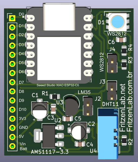
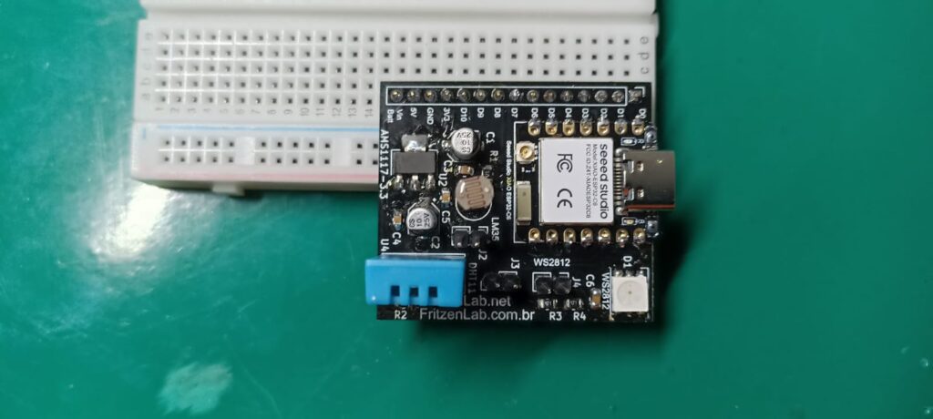
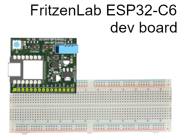
The board’s unique feature is that it can be connected directly to the Proboard without taking up much space (only one side, see image below). It also has an integrated 3.3V regulator (LM1117-3.3), so you can power it with 5V. ATTENTION: the IO pins are NOT 5V tolerant, only 3.3V.
It can also be powered directly by 3.3V or by battery (4.2V VIN input). It has three peripherals to make your life easier when testing: an analog LDR light sensor, a digital DHT11 temperature/humidity sensor and a WS2812 addressable LED (Neopixel).
IMPORTANT:
- If you do not want to use the WS2812 Neopixel, remove jumper J4
- If you do not want to use the DHT11 sensor, remove jumper J3
- If you do not want to use the LDR sensor, remove jumper J2
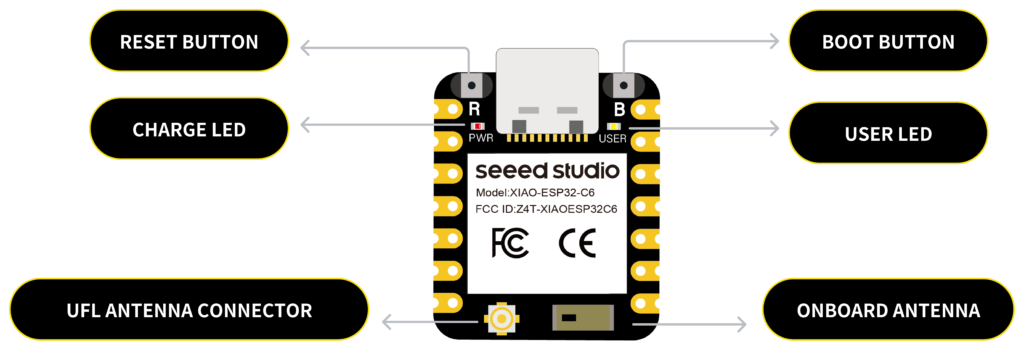
Pinout
Eleven (11) IO pins are available on the board’s breadboard connector, they are and their functions:
- D0:A0:GPIO 0 (digital, analog A0)
- D1:A1:GPIO 1 (digital, analog A1)
- D2:A2:GPIO 2 (digital, analog A2)
- D3:GPIO 21:SDIO_DATA1 (digital, SD card)
- D4:SDA:GPIO 22:SDIO_DATA2 (digital, i2c, SD card)
- D5:SCL:GPIO 23:SDIO_DATA3 (digital, i2c, SD card)
- D6:TX:GPIO 16 (digital, Serial TX)
- D7:RX:GPIO 17 (digital, Serial RX)
- D8:SCK:GPIO 19:SDIO_CLK (digital, SPI, SD card)
- D9:MISO:GPIO 20:SDIO_DATA0 (digital, SPI, SD card)
- D10:MOSI:GPIO 18:SDIO_CMD (digital, SPI, SD card)
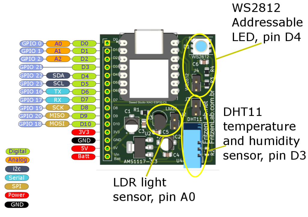
Onboard peripherals occupy the following pins:
- LDR: A0
- DHT11: D3
- WS2812: D4
Always remember that to be able to use these pins for other functions, remove jumpers J2, J3 and J4 from the board.
Schematic diagram
All the files for manufacturing this board are on this Github. The schematic diagram is seen below.
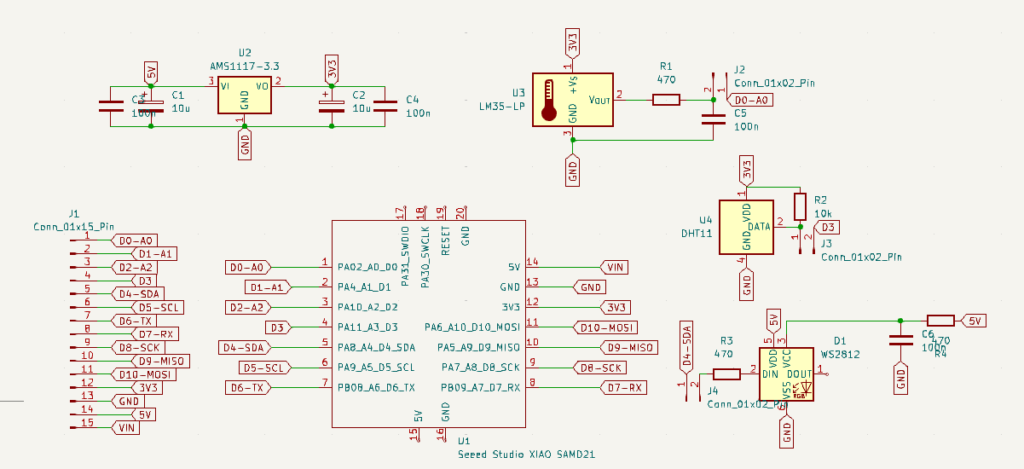
Note the 3.3V AMS1117-3.3 voltage regulator and its filter capacitors on the input and output. Also note the RC filter on the signal pin of the LDR light sensor. There is also a pull-up resistor on the signal pin of the DHT11 sensor.
Finally, note a current limiting resistor on the signal pin of the WS2812 neopixel addressable RGB LED, as well as an RC filter on its VCC pin. Now speaking of the ESP32, some pins on its footprint come from the circuit I referred to, and are not used here. This is the case of SWDIO and SWCLK, as well as +5V, GND and Reset that are not connected in the diagram above.
The schematic diagram of the Xiao ESP32-C6 module is here.
Power supply
According to the official SeeedStudio specifications, the Xiao ESP32-C6 board can be powered via a USB C cable (not included with the product), or by applying 5V to the VIN pin (up to 600mA).
If powered via the USB C cable, the WS2812b RGB LED would not work (since it requires 5V). There are also “Bat” pins on the Xiao ESP32-C6, but THEY ARE NOT AVAILABLE on my version of the board. These pins are located underneath and inaccessible.
DETAIL: to use the WS2812 (RGB LED), an external 5V power supply is required, coming from pins 14/15 (+5V/VIN) of the main breadboard connector.
The current consumption of the board when the ESP32-C6 is in “modem-sleep” (without WiFi) is around 30mA. In “deep-sleep” it can drop to 0.3mA (which is basically the consumption of the DHT11 sensor). The current consumption of the WS2812 RGB LED when turned on is around 33mA, according to this source.
Hardware configuration
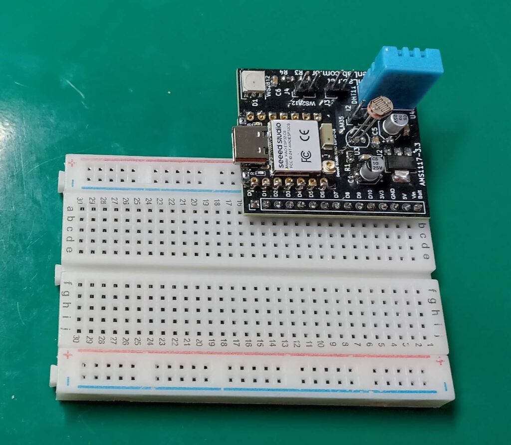
When connecting the board to a protoboard for use, some precautions must be taken:
- Power the board EITHER with a USB cable OR VIN (5V), never from more than one power source.
- If you are not going to use the WS2812b RGB LED, the LDR sensor or the DHT11 sensor, remove the respective jumpers.
- Only use sensors, actuators or modules that are powered at 3.3V, the board does not tolerate 5V on the GPIO pins. Some Arduino modules have specific pins to be powered with 3.3V. You can also use logic level converters.
- The board’s analog inputs also receive signals only up to 3.3V.
Arduino IDE programming
The Xiao ESP32-C6 board can be programmed via the Arduino IDE. The buttons required for programming are shown below.
You will need a USB Type-C cable to connect to your computer, as well as the Arduino IDE (software) installed. In June 2024, support for the ESP32-C6 was added to the Arduino IDE. In “File > Preferences” place the following line:
https://espressif.github.io/arduino-esp32/package_esp32_dev_index.jsonThen go to “Tools > Board > Board Manager” and type “ESP32”. If you have any ESP32 boards installed in the IDE, remove them. Install the Espressif package with version at least “3.0.0-rc1” (older versions do not support the ESP32-C6 board).
Connect the USB C cable to the board and to the computer. Run the “Blink” or “BlinkWithoutDelay” example, leaving the LED pin as “LED_BUILTIN” or pin 15, as seen below.
Micropython programming
Apparently as of the end of June 2024 there is no official support for the ESP32-C6 in microPython, according to this Github thread.
CircuitPython programming
There is a port of Adafruit’s CircuitPython for the ESP32-C6-DevKitC-N4 board, here at this link. The official Adafruit guide on how to flash the bootloader to the board is here. I made it work (sort of) here.
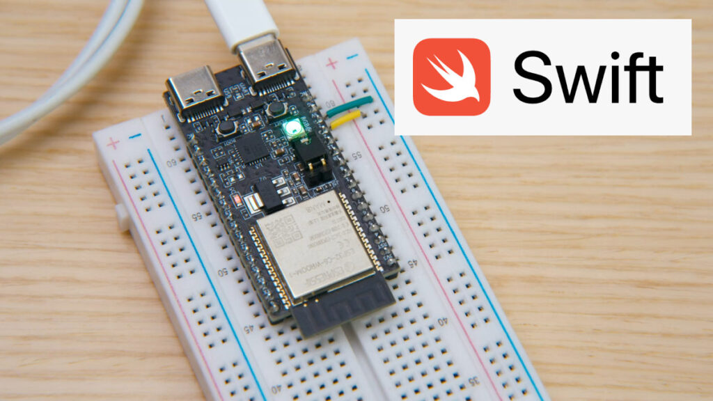
Swift (Apple) programming
According to this source, the ESP32-C6 supports programming in embedded Swift, a subset of Apple’s programming language for its products. Here is a “getting started guide” that links to a repository. The linked Github has an example of controlling an RGB LED strip with the ESP32-C6.
Internal/external antenna
This ESP32-C6 Xiao board from SeeedStudio has the option to use the internal WiFi antenna (mounted on the board) or connect an external one. This selection is made via software through the GPIO14 pin, according to the board’s schematic diagram. GPIO14 at 0 uses the internal antenna (this is the default) and GPIO14 at 1 allows an external antenna. The antenna is sold separately by SeeedStudio, here.
Your ESP32-C6 as a WiFi modem for Raspberry Pi
Xiao ESP32-C6 onboard LED blinking
The ESP32-C6 board I’m using is from SeeedStudio’s Xiao line. It has a yellow LED onboard (mounted on the board), which we’ll make blink from now on. Open the most up-to-date Arduino IDE (it can’t be versions 1.8.x), and paste the code below.
// constants won't change. Used here to set a pin number:
const int ledPin =  15;// the number of the LED pin

// Variables will change:
int ledState = LOW;             // ledState used to set the LED

// Generally, you should use "unsigned long" for variables that hold time
// The value will quickly become too large for an int to store
unsigned long previousMillis = 0;        // will store last time LED was updated

// constants won't change:
const long interval = 1000;           // interval at which to blink (milliseconds)

void setup() {
  // set the digital pin as output:
  pinMode(ledPin, OUTPUT);
}

void loop() {
  // here is where you'd put code that needs to be running all the time.

  // check to see if it's time to blink the LED; that is, if the difference
  // between the current time and last time you blinked the LED is bigger than
  // the interval at which you want to blink the LED.
  unsigned long currentMillis = millis();

  if (currentMillis - previousMillis >= interval) {
    // save the last time you blinked the LED
    previousMillis = currentMillis;

    // if the LED is off turn it on and vice-versa:
    if (ledState == LOW) {
      ledState = HIGH;
    } else {
      ledState = LOW;
    }

    // set the LED with the ledState of the variable:
    digitalWrite(ledPin, ledState);
  }
}
Note that I put the “ledPin” pin as 15, where the LED is on our board. I didn’t put the “D” in front because this pin is not available on the breadboard connector, it is an “internal” pin. I could still have put “LED_BUILTIN”. So save the sketch, connect the USB-C cable to the ESP32-C6 and upload.
Using the onboard LDR analog sensor
The analog LDR light sensor (mounted on the board) is powered by 5V and is connected to pin A0 of the ESP32-C6. According to the chip’s reference manual, the analog values are converted to up to 4096 (12-bit) integers.
The code below reads the LDR value every 500ms (half a second) and prints it to the serial monitor, at a speed of 115200bps. My reference for the code was this link.
// LDR is connected to GPIO0 (Analog A0)
const int LDRPin = A0;

// variable for storing the potentiometer value
int LDRValue = 0;

void setup() {
  Serial.begin(115200);
  delay(1000);
}

void loop() {
  // Reading potentiometer value
  LDRValue = analogRead(LDRPin);
  Serial.println(LDRValue);
  delay(500);
}
ESP32-C6 internal temperature sensor
The ESP32-C6 chip has an internal temperature sensor, capable of displaying the chip’s temperature with great accuracy between -10ºC and +80ºC. Following this reference, copy the code below to a text file and name it temp_sensor.h .
/*
 * SPDX-FileCopyrightText: 2010-2021 Espressif Systems (Shanghai) CO LTD
 *
 * SPDX-License-Identifier: Apache-2.0
 */

#pragma once

#include <stdint.h>
#include "esp_err.h"

#ifdef __cplusplus
extern "C" {
#endif

/**
 * @brief temperature sensor range option.
 */
typedef enum {
    TSENS_DAC_L0 = 0, /*!< offset = -2, measure range: 50℃ ~ 125℃, error < 3℃. */
    TSENS_DAC_L1,     /*!< offset = -1, measure range: 20℃ ~ 100℃, error < 2℃. */
    TSENS_DAC_L2,     /*!< offset =  0, measure range:-10℃ ~  80℃, error < 1℃. */
    TSENS_DAC_L3,     /*!< offset =  1, measure range:-30℃ ~  50℃, error < 2℃. */
    TSENS_DAC_L4,     /*!< offset =  2, measure range:-40℃ ~  20℃, error < 3℃. */
    TSENS_DAC_MAX,
    TSENS_DAC_DEFAULT = TSENS_DAC_L2,
} temp_sensor_dac_offset_t;

/**
 * @brief Configuration for temperature sensor reading
 */
typedef struct {
    temp_sensor_dac_offset_t dac_offset;    /*!< The temperature measurement range is configured with a built-in temperature offset DAC. */
    uint8_t clk_div;                        /*!< Default: 6 */
} temp_sensor_config_t;

/**
 * @brief temperature sensor default setting.
 */
#define TSENS_CONFIG_DEFAULT() {.dac_offset = TSENS_DAC_L2, \
                                .clk_div = 6}

/**
 * @brief Set parameter of temperature sensor.
 * @param tsens
 * @return
 *     - ESP_OK Success
 */
esp_err_t temp_sensor_set_config(temp_sensor_config_t tsens);

/**
 * @brief Get parameter of temperature sensor.
 * @param tsens
 * @return
 *     - ESP_OK Success
 */
esp_err_t temp_sensor_get_config(temp_sensor_config_t *tsens);

/**
 * @brief Start temperature sensor measure.
 * @return
 *     - ESP_OK Success
 *     - ESP_ERR_INVALID_ARG
 */
esp_err_t temp_sensor_start(void);

/**
 * @brief Stop temperature sensor measure.
 * @return
 *     - ESP_OK Success
 */
esp_err_t temp_sensor_stop(void);

/**
 * @brief Read temperature sensor raw data.
 * @param tsens_out Pointer to raw data, Range: 0 ~ 255
 * @return
 *     - ESP_OK Success
 *     - ESP_ERR_INVALID_ARG `tsens_out` is NULL
 *     - ESP_ERR_INVALID_STATE temperature sensor dont start
 */
esp_err_t temp_sensor_read_raw(uint32_t *tsens_out);

/**
 * @brief Read temperature sensor data that is converted to degrees Celsius.
 * @note  Should not be called from interrupt.
 * @param celsius The measure output value.
 * @return
 *     - ESP_OK Success
 *     - ESP_ERR_INVALID_ARG ARG is NULL.
 *     - ESP_ERR_INVALID_STATE The ambient temperature is out of range.
 */
esp_err_t temp_sensor_read_celsius(float *celsius);

#ifdef __cplusplus
}
#endif
Place the file above in the same folder where you will save the file below. Now download the code below to the ESP32-C6 board, changing the path (URL) of the first line to where on your computer you saved temp_sensor.h.
#include "C:\Users\Clovisf\Documents\Fritzenlab\ESP32-S2-Franzinho-WiFi\temp_sensor.h"

void initTempSensor(){
    temp_sensor_config_t temp_sensor = TSENS_CONFIG_DEFAULT();
    temp_sensor.dac_offset = TSENS_DAC_L2;  // TSENS_DAC_L2 is default; L4(-40°C ~ 20°C), L2(-10°C ~ 80°C), L1(20°C ~ 100°C), L0(50°C ~ 125°C)
    temp_sensor_set_config(temp_sensor);
    temp_sensor_start();
}

void setup() {
  Serial.begin(115200);
  initTempSensor();
}

void loop() {
  Serial.print("Temperature: ");
  float result = 0;
  temp_sensor_read_celsius(&result);
  Serial.print(result);
  Serial.println(" °C");
  delay(5000);
}
Your serial monitor is expected to show the chip’s internal temperature as follows:

Using the onboard DHT11 digital temperature sensor
The DHT11 sensor is capable of providing ambient temperature and humidity readings digitally via just one pin. In the case of our board, it is connected to pin D3, already having a 10k Ohm pull-up resistor. I have already written here on the blog about the DHT11 with the ESP32-S2 chip, the code will be exactly the same. What changes is that we will define the pin as 3.
#include "DHT.h"
#define DHTPIN D3 // Digital pin connected to the DHT sensor
// Uncomment whatever type you're using!
#define DHTTYPE DHT11 // DHT 11
//define DHTTYPE DHT22 // DHT 22 (AM2302), AM2321
//#define DHTTYPE DHT21 // DHT 21 (AM2301)
// Connect pin 1 (on the left) of the sensor to +5V
// NOTE: If using a board with 3.3V logic like an Arduino Due connect pin 1
// to 3.3V instead of 5V!
// Connect pin 2 of the sensor to whatever your DHTPIN is
// Connect pin 3 (on the right) of the sensor to GROUND (if your sensor has 3 pins)
// Connect pin 4 (on the right) of the sensor to GROUND and leave the pin 3 EMPTY (if your sensor has 4 pins)
// Connect a 10K resistor from pin 2 (data) to pin 1 (power) of the sensor
// Initialize DHT sensor.
// Note that older versions of this library took an optional third parameter to
// tweak the timings for faster processors. This parameter is no longer needed
// as the current DHT reading algorithm adjusts itself to work on faster procs.
DHT dht(DHTPIN, DHTTYPE);
void setup() {
Serial.begin(115200);
Serial.println(F("DHTxx test!"));
dht.begin();
}
void loop() {
// Wait a few seconds between measurements.
delay(2000);
// Reading temperature or humidity takes about 250 milliseconds!
// Sensor readings may also be up to 2 seconds 'old' (its a very slow sensor)
float h = dht.readHumidity();
// Read temperature as Celsius (the default)
float t = dht.readTemperature();
// Read temperature as Fahrenheit (isFahrenheit = true)
float f = dht.readTemperature(true);
// Check if any reads failed and exit early (to try again).
if (isnan(h) || isnan(t) || isnan(f)) {
Serial.println(F("Failed to read from DHT sensor!"));
return;
}
// Compute heat index in Fahrenheit (the default)
float hif = dht.computeHeatIndex(f, h);
// Compute heat index in Celsius (isFahreheit = false)
float hic = dht.computeHeatIndex(t, h, false);
Serial.print(F("Humidity: "));
Serial.print(h);
Serial.print(F("% Temperature: "));
Serial.print(t);
Serial.print(F("°C "));
Serial.print(f);
Serial.print(F("°F Heat index: "));
Serial.print(hic);
Serial.print(F("°C "));
Serial.print(hif);
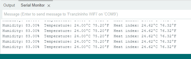
Serial.println(F("°F"));
}We expect a result on the serial monitor as shown in the image below, showing humidity in percentage, temperature in ºC and ºF and heat index.
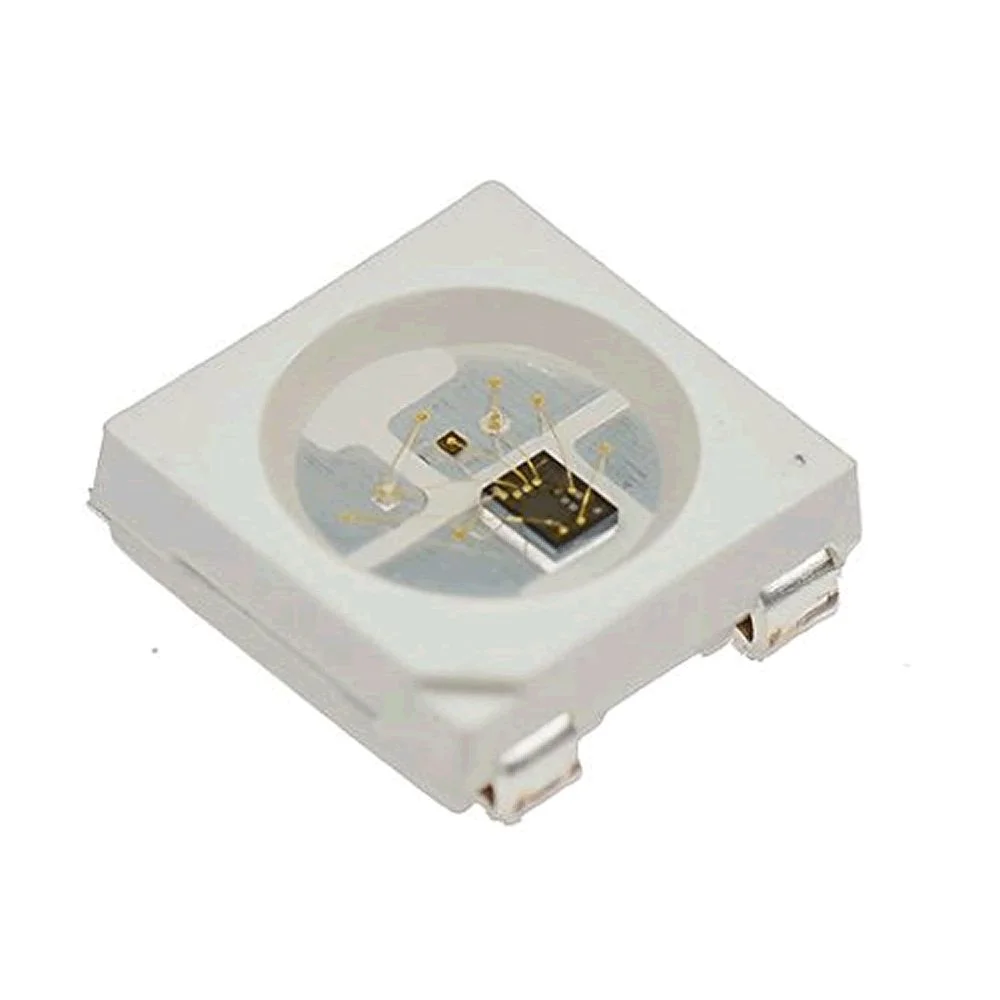
WS2812b addressable RGB LED
This ESP32-C6 development board features a WS2812b addressable RGB LED mounted on it, connected to pin D4. The LED is capable of reproducing 16 million colors at at least 400Hz and with 256 brightness levels.
The code for testing the LED is shown below. First, you need to install the “Adafruit Neopixel” library in the Arduino IDE, in “Sketch > Include library > Manage libraries…”. My reference for this tutorial is here.
#include <Adafruit_NeoPixel.h>      //Adiciona a biblioteca Adafruit NeoPixel
#define D_in D4       //Nomeia o pino 6 do Arduino
#define qtdeLeds 1    //Informa a quantidade de LEDs que serão ligados em cascata
Adafruit_NeoPixel pixels(qtdeLeds, D_in);     //Instancia o objeto "pixels", informando a quantidade e o pino de sinal
void setup() {
  pinMode(D_in, OUTPUT);      //Configura o pino 6 como saída
  pixels.begin();             //Inicia o objeto "pixels"
}
void loop() {
  pixels.clear();      //desliga todos os LEDs
  for(int i=0; i<qtdeLeds; i++){        //para i = 0, se i menor que a quantidade de leds, incremente 1 em i
    pixels.setPixelColor(i, pixels.Color(255, 0, 0));     //liga o led correspondente ao número da variável i na cor vermelha
    pixels.show();      //executa os parâmetros do comando acima
    delay(500);         //Aguarda 500 milissegundos

    pixels.setPixelColor(i, pixels.Color(0, 255, 0));     //liga o led correspondente ao número da variável i na cor verde
    pixels.show();      //executa os parâmetros do comando acima
    delay(500);         //Aguarda 500 milissegundos

    pixels.setPixelColor(i, pixels.Color(0, 0, 255));     //liga o led correspondente ao número da variável i na cor azul
    pixels.show();      //executa os parâmetros do comando acima
    delay(500);         //Aguarda 500 milissegundos
  }
}
Note that we defined the “D_in” pin as 4 (pin 4 of ESP32-C6) and “qtdeLeds” as 1, just one unit on the board. We are making a simple RGB code, where every 500ms a color (red, green, blue) is shown.
I2C communication test
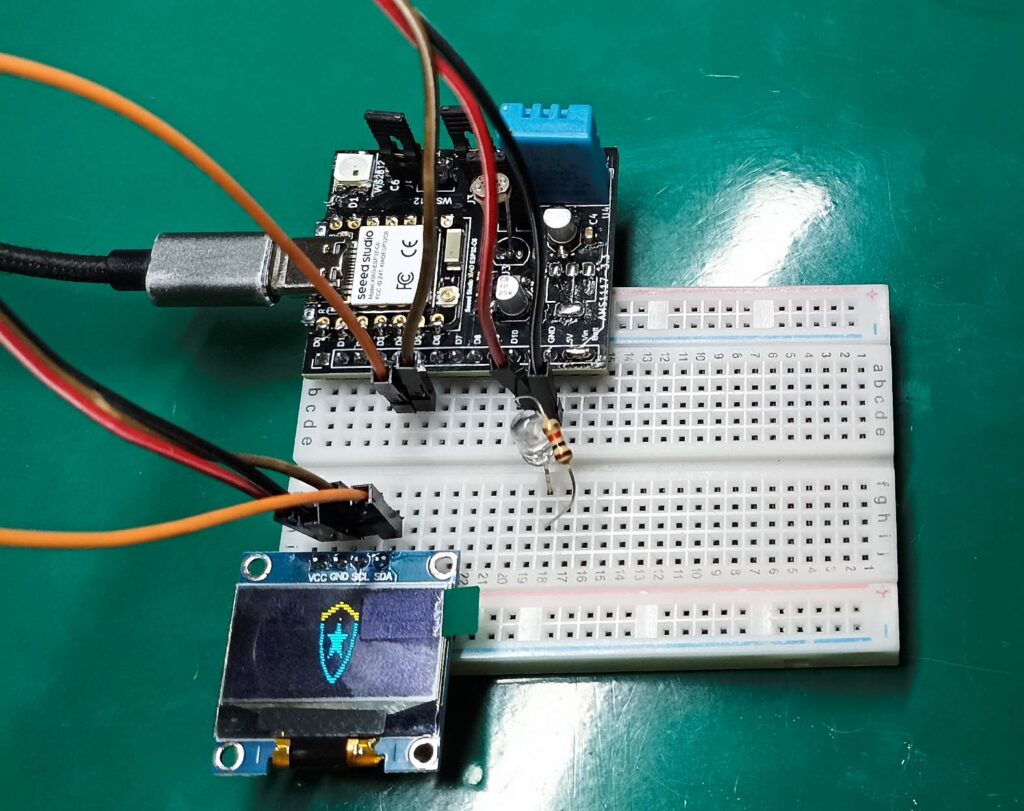
An i2c communication port is available on the ESP32-C6 dev board, on pins D4 (SDA) and D5 (SCL). The test code for Arduino is the same as found in this article, seen in the image below. It is a 0.96″ two-color OLED display (yellow and blue).
WiFi connection
We can use the same Arduino sketch as any other ESP32 to test WiFi. The code below scans for available networks, and was inspired by this article.
#include "WiFi.h"

void setup() {
  Serial.begin(115200);

  // Set WiFi to station mode and disconnect from an AP if it was previously connected
  WiFi.mode(WIFI_STA);
  WiFi.disconnect();
  delay(100);

  Serial.println("Setup done");
}

void loop() {
  Serial.println("scan start");

  // WiFi.scanNetworks will return the number of networks found
  int n = WiFi.scanNetworks();
  Serial.println("scan done");
  if (n == 0) {
      Serial.println("no networks found");
  } else {
    Serial.print(n);
    Serial.println(" networks found");
    for (int i = 0; i < n; ++i) {
      // Print SSID and RSSI for each network found
      Serial.print(i + 1);
      Serial.print(": ");
      Serial.print(WiFi.SSID(i));
      Serial.print(" (");
      Serial.print(WiFi.RSSI(i));
      Serial.print(")");
      Serial.println((WiFi.encryptionType(i) == WIFI_AUTH_OPEN)?" ":"*");
      delay(10);
    }
  }
  Serial.println("");

  // Wait a bit before scanning again
  delay(5000);
}
As a way to test the ESP32-C6 connection to WiFi, we will obtain weather data from the Open Weather Map website, as per this tutorial.
ESP32-C6’s bluetooth connection
Until the closing of this text I was unable to make Bluetooth work with my Xiao ESP32-C6, it always gives an error when compiling in the Arduino IDE.
Generating true random numbers
Example in this link and with information from the technical reference manual. When porting the random number function to the Arduino language, the random() function was overwritten with the features of esp_random(). This makes the ESP32’s way of generating random numbers identical to that of Arduino.
void setup()
{
  Serial.begin(115200);
}

void loop()
{
  auto randomNumber0_10 = random(10); // random number between 0-10
  auto randomNumber10_20 = random(10, 20); // random number between 10-20
  Serial.println(randomNumber0_10);
  Serial.println(randomNumber10_20);

  delay(1000);
}
In the example above, two random numbers are generated and printed on the serial monitor: one between 0 and 10 and the other between 10 and 20. All this every second.
Matter ecosystem support
Matter is an IP-based protocol whose goal is to create connected things. All this through the concept of IoT. Although it is available in the ESP-IDF ecosystem, according to this link it is not yet possible to use it with the Arduino IDE. With ESP-IDF this is a good resource to start with, there is firmware ready to use on the ESP32-C6.
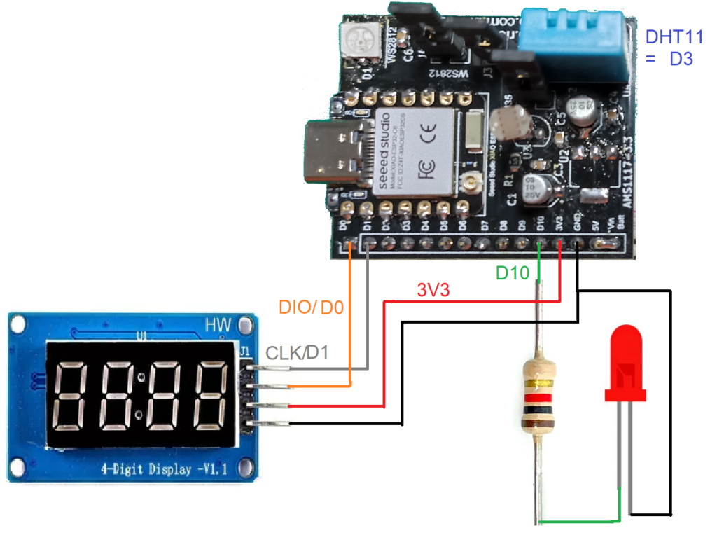
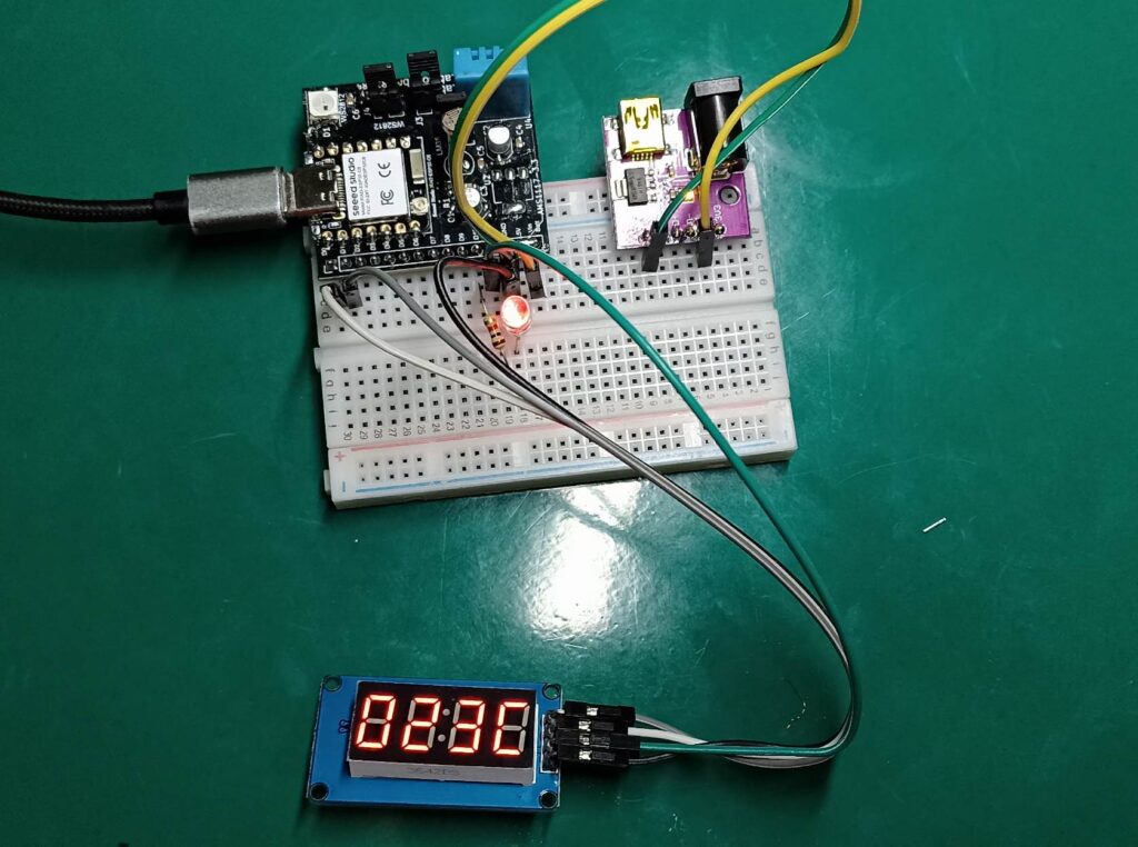
Project example: temperature display
Project link here (Portuguese).