

Let me present you a small yet powerful sensor, capable of assessing air quality. The TGS2602 is capable of reacting to and detecting odorous gases like ammonia, Ethanol and hidrogen sulfide. Such gases could be found in dangerous concentrations in tightly closed office spaces, for example.
Setting up a mini weather station inside your living space or office could mean breathing a better air. This is where sensors like this TGS2602 come in handy. An easy to use and setup-free type of sensor, ready to connect and use as you wish.
The actual sensor is mounted inside a metal case with four terminals. The model I bought on Aliexpress (link here) comes in a nice purple PCB (print circuit board). It features an LM311 operational amplifier with an adjustable threshold. This means you can use its “DOUT” output as an indicative of the sensor surpassing a certain contamination level.
But our experiment today will make use of the “AOUT” output, which is analog. That means we will be able to use an analog input of our ESP32-C6 microcontroller to read variations in odorous gases presence. You could of course use any other microcontroller that has an analog input, which most of them have. For you to understand this sensor a bit better, let me point its characteristics to you.
It basically features two resistors inside the case, there are no electronics, circuitry, nothing. One resistor is a 59 Ohm (typically) with an allowed current of 56 +/- 5 mA. That roughly adds up to 280mW, enough to heat the whole case to the touch.
Such resistor serves to heat the sensing “resistor”, the second and final element inside the sensor case. I quoted the word resistor because it is really a semiconductor, whose function is to vary its own resistance with the presence of odorous gases. So basically the power resistor heats the sensing resistor to a optimal point, at which it can then sense gases for us.
But what about the air quality sensor?
According to TGS2602’s datasheet from this link, you can correlate the sensing resistor value ratio to the gas concentration in ppm (parts per million). There is even a chart for that, reproduced below. Note the Rs/R0 ratio, where Rs is the sensor resistance at any given moment and R0 is the sensing resistor resistance under clean air.
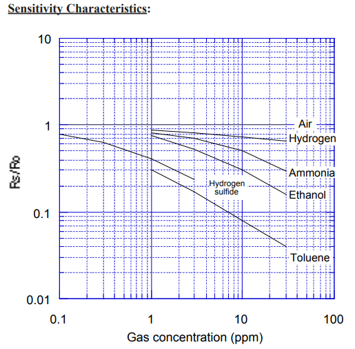
You can see the “Air” text in the center right part, indicating an Rs/R0 of 1. Then below that you see a couple of gases and their curves, all featuring Rs/R0 below one (1) unit. What does that mean for this sensor and for us? This is actually very important that you understand:
Analog sensors such the TGS2602 will not give you firm values of any type of gases. If you want reasonable Ammonia values for example, you will have to fully calibrate the sensor for such gas.
That holds true for any and every analog output sensor, such as the Mics-5524 of the video below. P.S: keep and eye on the blog for a Mics-5524 article in the near future.
Since I don’t have access to calibration laboratories, this article will focus on reading and presenting the actual resistance value of the sensor. TGS2602’s datasheet brings the equation for us:
Rs = ((Vc / VRL) - 1) * RL- Where “Vc” is the supply voltage, recommended to be 5V.
- Voltage “VRL” is what the ESP32-C6 will read with its analog input. It is the voltage over the “RL” resistor on the sensor board.
- Resistance “RL” is 3.9k Ohm, which was defined by the sensor board manufacturer. Sensor’s datasheet asks for a minimum resistor value of 450 Ohm.
So basically we supply the circuit with 5V, read the “AOUT” value from the sensor with an analog input of our ESP32 and know the “RL” value to be 3.9k Ohm. That is enough to determine the “Rs” sensor resistance.
Hardware for the experiment
As you already know from this, this and many other articles, I generally like to keep my assemblies simple. This is since I like to test one “thing” at a time, be it a sensor, a new microcontroller, etc. This time will not be different, we will test our TGS2602 sensor by itself, connected to a Xiao ESP32-C6.
The only “other” thing on our breadboard will be a 5mm red LED, just blinking for fun. Speaking about breadboards, I could have used a 400 points one for this build, since I am using my own home-made ESP32-C6 board (more here). That is special because it takes up only one spot each row of the breadboard, leaving space for many other things.
I picked a 800 points breadboard because I had one laying around. Besides that, I am supplying the whole circuit from USB. Every SeeedStudio Xiao board features direct USB connection for data and power. The whole circuit is below for you to have a look and copy, enjoy!.
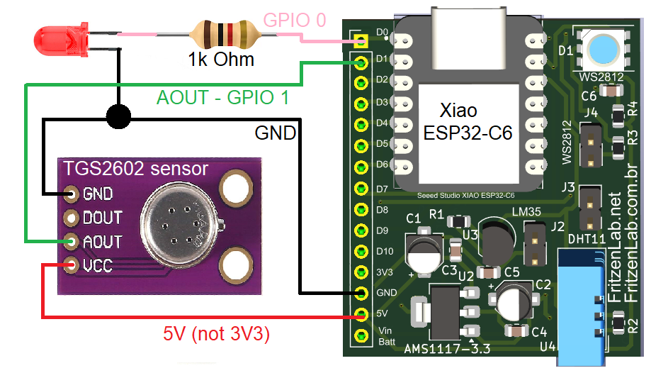
Please not this little detail related to power: the TGS2602 sensor is supplied with 5V, not 3V3. Its datasheet specifically points that out, since that voltage is mainly used to power the heat element.
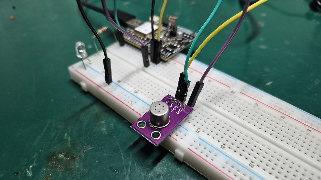
Also please note that the sensor is interfaced with the ESP32-C6 via a single analog input. An important note fits here: the chart above (from the sensor datasheet) brings the Rs/R0 to 0.03 with Toluene presence. That ratio means Rs (sensor resistance) can be as low as 0.03 * 10000 = 300 Ohm. Since the RL resistor outside the sensor is 3.9k Ohm, that potentially brings the analog voltage output of the sensor to 4.64V.
So if you are planning to sense Toluene, do one of three things:
- Decrease the value of RL to less than 3.9k Ohm (so essentially modify the sensor board) or
- Use a microcontroller that can read up to 5V analog or even
- Add a voltage divider circuit between the sensor and the 3V3 microcontroller.
But of course if you stay away from Toluene exposition, chances are that your Rs/R0 will be bigger than 0.15. That means a maximum analog voltage output from the sensor at around 3.6V. Essentially what I want to say is: if you get out-of-range measurements, over 3.3V, you know you have to do one of three things from above to your air quality sensor.
Firmware/code for the sensor
TGS2602 sensor is completely analog, meaning there are no pre or post processing and in fact no electronics inside it. It features the single sensing resistor Rs and nothing else. That means we don’t have to use a library to interface with it, no worring with timing or protocols.
In fact all I did in my code, which is available below and in this GitHub, was to calculate Rs. Component’s datasheet itself brought the equation for us, all I had to do was translate that into C++/Arduino code. I have brought you the full code for the equation, along with explanations in the sections above.
Just for fun and games and to indicate that the microcontroller is running, I implemented a LED blink. The whole code is non-blocking, meaning I have not used any delay(). Instead I used millis() and an IF() clause, as you have already seen here. Full code is below:
#define TGS2602pin 1
#define LED 0

unsigned long tgs2602Time = 0;
unsigned long ledTime = 0;
float analogValue = 0;
uint8_t ledStatus = 0;
uint16_t RL = 3900;

void setup() {
  // put your setup code here, to run once:
  Serial.begin(115200);
  pinMode(LED, OUTPUT);
  analogReadResolution(12);
}

void loop() {
  // put your main code here, to run repeatedly:
  if(millis() - tgs2602Time > 1000){
    tgs2602Time += 1000;
    // Sensor resistance (Rs) = ((Vsupply / VRL) - 1) * RL
    // Where Vsupply= 5V, VRL= (analogRead12bit * 3.3 / 4095) and RL= 3900 Ohm
    analogValue = ((5.00 / (analogRead(TGS2602pin) * 3.3 / 4095.00)) - 1) * RL;
    Serial.print("TGS2602 Rs:");
    Serial.println(analogValue, 2);
  }
  if(millis() - ledTime > 150){
    ledTime += 150;
    if(ledStatus == 0){
      ledStatus= 1;
    }else{
      ledStatus= 0;
    }
    digitalWrite(LED, ledStatus);
  }

}
So essentially I make a full sensor reading and resistance calculation every second (1000 ms). LED changes state every 150 ms, meaning a 300 ms full cycle (3.33 Hz). One important detail: my ESP32-C6 allows me to decide its analog input reading resolution, up to 12 bits. I do that by adding this to setup():
analogReadResolution(12);If you are using for example an Arduino UNO, that line does not apply and will not even compile. Remove it. Arduino UNO has analog inputs in 10 bit resolution, case in which you will have to use 5V and 1024 integers, so instead of:
analogValue = ((5.00 / (analogRead(TGS2602pin) * 3.3 / 4095.00)) - 1) * RL; // this is for ESP32 or any other 3.3V boardFor Arduino UNO you will do:
analogValue = ((5.00 / (analogRead(TGS2602pin) * 5 / 1024.00)) - 1) * RL; // this is for Arduino UNO or any other 5V boardTesting the TGS2602 sensor
I am using the software Arduino IDE version 2.3.10 for this experiment. You can use any version above 1.8.x, as you wish. Copy the full code above and paste it into your Arduino IDE. Plug your ESP32-C6 board into the computer via USB cable. Select the correct board in “Tools > Board”.
Now press the “->” green arrow (upload) in the top left of the Arduino IDE. After a while you may get a success message similar to this one:
rote 270384 bytes (148150 compressed) at 0x00010000 in 2.0 seconds (1084.7 kbit/s).
Verifying written data...
Hash of data verified.

Hard resetting via RTS pin...
Then open the Arduino IDE serial plotter in “Tools > Serial plotter”. You will start to see something similar to the image below.
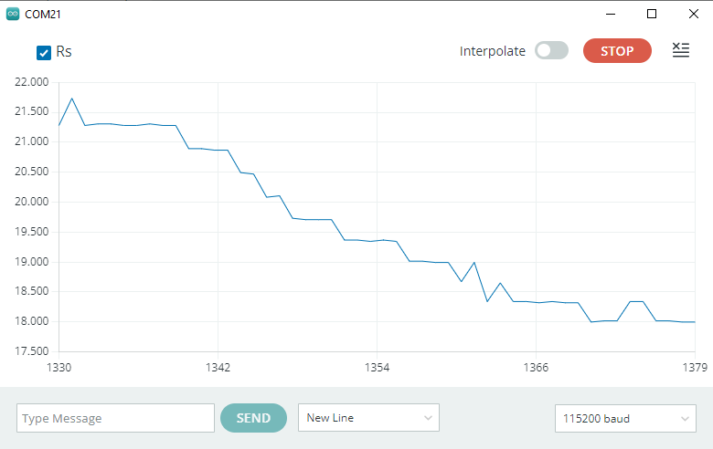
My code has no averaging or filtering, those values above are straight readings from the sensor every second. You can see the value varying between 18k and 21.5k Ohm. There is simply no way of knowing from which odorous gas this value comes from. This is since this sensor presents us with a single “dimension”, which is sensor resistance.
What we can say is that the air in the readings above is “clean”. This is because for example 21.5k Ohm (Rs) divided by R0 (10k) results in 2.15. That sits above one (1) in the chart I present in the beginning of the article. It features no gases present when the value is above 1.
The chart below is what happened when I exposed the TGS2602 sensor to 70% ethyl alcohol: the resistance immediately jumped down to around 2.4k Ohm.
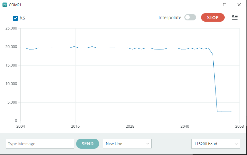
I then submitted the sensor the household bleach, in which case the Rs resistance jumped up to 34k Ohm. That means an Rs/R0 of around 3.4, still in the “clean air” part of the chart. I cannot explain why this happened, since household bleach can evaporate as an odorous gas and be dangeours to humans.
I made a video illustrating how to use this sensor, it is located at the beginning of this article. If you want to buy a TGS2602 to experiment with, use my Aliexpress link. As always, if you want to comment, please do it in the form below or you my Youtube Channel. See you guys in the next article!.