

Implementing if not the smallest thermometer but the simplest, featuring an NTC temperature sensor, two LEDs and one Attiny85 microcontroller. The idea is to make a thermometer that is cheap to build, small enough to throw around and simple to program.
How does it work? two LEDs, one is the dozen the other is the units. For example to show 17ºC, LED dozen will blink 1 time and LED units will blink 7 times.
If you are a blog reader, you know that I love to talk about temperature sensor. Just have a look at how many results are there in this search query for “temperature”. I have tested, programmed and used a bunch of such sensor, the likes of LM35, NTC, BMP280, AHT21 and so on.
Today’s post is all about a little gadget I have been wanting to make for quite some time. One that is as simple as connecting to any USB port and using. The idea is to have a way to quickly check room temperature. For that I thought of using the small but powerful Attiny85.
This is since we do not need internet connection, otherwise I would surely throw an ESP32 in. But no, all we need is a microcontroller powerful enough to calculate the curve of a NTC thermistor. Speaking of which, did you know we have talked about NTC’s in the past? just check it here.
NTC stands for “negative temperature coefficient”, meaning its resistance decreases with temperature increasing. It is a simple enough sensor that a single series resistor makes it possible to read it. The one I am using is the B57421V2103J62 from TDK, whose datasheet is here. It is a 0805 SMD package, just because. Of course you can use any other model you have at hand, just be mindful of its 25ºC resistance and Beta value.
How does the Smallest thermometer work?
For me the coolest part of this project is its temperature display. I will start by saying it is just two 5mm LEDs, any color you have available. Any ideas on how it works to show temperature?. Image below says it all:
- The first LED is the dozen,
- The second LED is the units,
- So for example for 25ºC the dozen LED will blink 2 times and the units LED will blink 5 times.
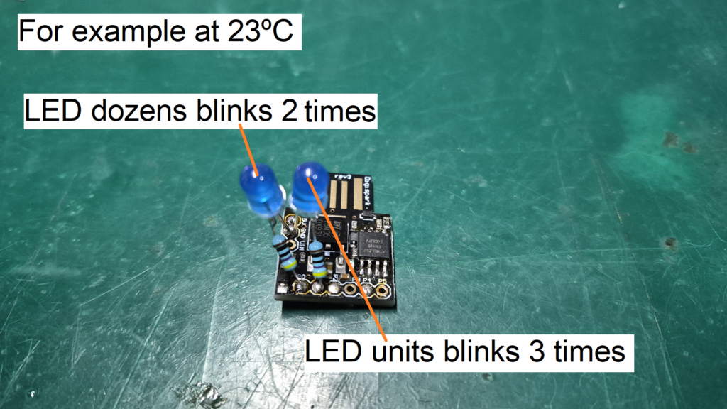
So basically things happen step by step. First an analog input of the Attiny85 reads the resistor divider of the NTC thermistor + 10k resistor. It then applies the Steinhart-Hart equation to obtain temperature in Kelvin. Next step is to convert from Kelvin into Celsius, then divide the number into the “dozen” digit and the “unit” digit.
Once you have two integers containing the “dozen” and “unit”, I devised an algorithm to make two LEDs blink accordingly. That does not happen at the same time, one LED actually blinks at a time. First the “dozen” LED will make its turn, then the “unit” LED comes into play.
In between a complete round there is some waiting time, to actually mark the finishing of a cycle. That time is precisely one second. The time it takes for each blink to happen (each individual quantity) is 0.4 seconds. So for example at 17ºC, each one of the blinks of the “unit” 7 takes 0.4 seconds.
It also means that for example to show 19ºC will take longer than to show 11ºC. Every one of the 9 “units” will take 0.4 seconds. That is by design, just to keep things readable and organized.
Hardware/assembling
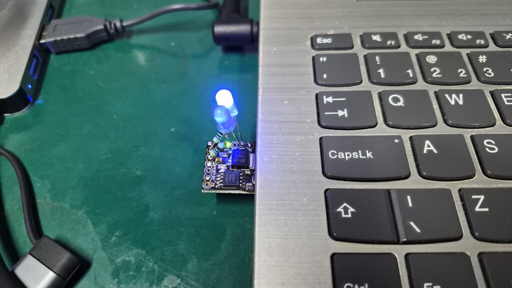
Our Smallest thermometer is relatively simple to assemble. Only thing that complicates it a bit is that it all has to fit on top of the Digispark Attiny85 board. One does not have to make any modification to the board itself, just solder all components in the right places.
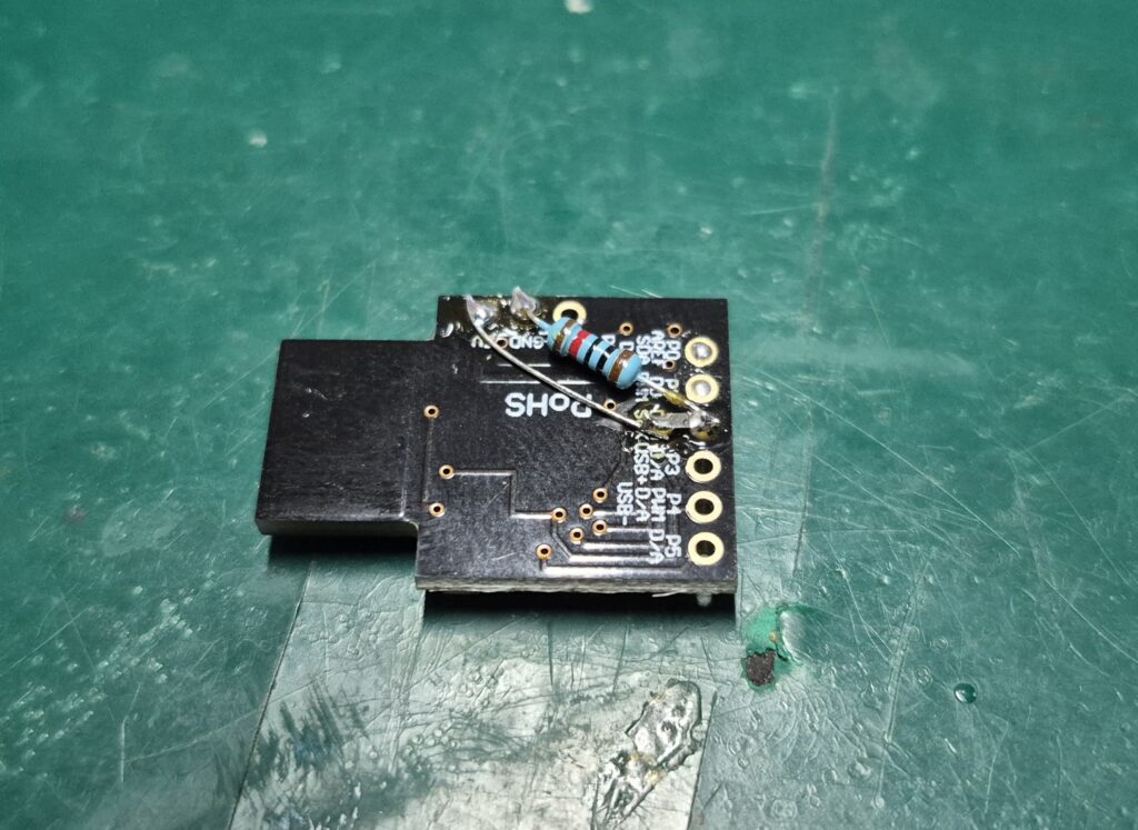
I made a desing decision that came back to bite me, but that is part of doing engineering. I decided to use the NTC thermistor I had at hand at the moment, a 0805 SMD one. Since I did not want anything “flying” around the board, I soldered the NTC thermistor touching the printed circuit board of the Digispark Attiny85.
Then during testing I observed that its temperature readings were a bit too high. That is in comparison to the free air temperature I was measuring with my Pomodoro project, in the same room. Then it clicked, the reason for that is that the Attiny85 board has, besided the microcontroller itself, also a 7805 voltage regulator.
Also the fact that this Attiny85 board connects straight into the USB of my laptop, makes the NTC absorb and measure all that heat at once. So for example at a given moment my Pomodoro project was measuring room temperature at 24.3ºC. The smallest thermometer was measuing 31ºC at the same moment.
That means 6+ ºC above free air, just because the NTC thermistor is touching the Digispark Attiny85 board itself.
I wrote all of that just to say that this project’s temperature readings will be a bit higher than the “real thing”
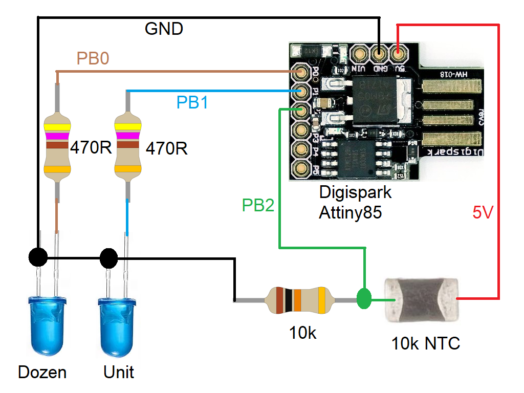
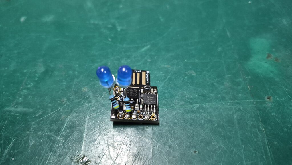
Back to hardware, the pin definition for this project had to be carefully done, since all I had was 5 pins at most. I ended up routing the analog input on pin PB2, LED dozens on pin PB0 and LED units on pin PB1. I used two 5mm blue LED’s, each with a 470 Ohm resistor in series.
The NTC thermistor features a 10k Ohm resistor in series. I picked a 1% tolerance one, just to bring a bit more reading precision to the table. As stated above, power supply comes to the Attiny85 straight via USB, offering 5V for the whole circuit. Full schematic diagram is seen below, along with some pictures of the actual prototype.
Firmware/code
As stated before, there are a couple of intersting parts of this project. Actually two parts to be honest: the Steinhart-Hart equation and the LED blinking mechanism. Those five lines are the juice of the equationing. Just a couple of mathematics and you get an integer with your Celsius temperature.
double v = (vcc*soma)/(nAmostras*1024.0);
    double rt = (vcc*R)/v - R;

    double t = beta / log(rt/rx);
    t= t - 273;
    temperature = int(t);
The lines of code below are the ones responsible for getting the temperature integer and blinking both LEDs. I am proud to say that I devised that algorithm myself, no help from the internet. That is something I have been enjoying to do over the years, think through a problem and solve it my way. May not be the best of the most elegant solution, but it is mine.
if(blinkingtens == true && blinkingunits == false){
      if(enteredtens == false){
        enteredtens = true;
        doubletens = 2 * tens;
        if(doubletens == 0){
          doubletens= 1;
        }
      }
      doubletens --;
      if(doubletens != 0){
        digitalWrite(pinZero, !digitalRead(0));
      }else{
        blinkingunits = true;
        blinkingtens = false;
      }

    }else if(blinkingunits == true && blinkingtens == false){
      blinkingtens= false;
      if(enteredunit == false){
        enteredunit = true;
        doubleunit = 2 * unit;
        if(doubleunit == 0){
          doubleunit= 1;
        }
      }
      doubleunit --;
      if(doubleunit != 0){
        digitalWrite(pinUno, !digitalRead(1));
      }else{
        waittime = true;
        blinkingunits = false;
        startedwait = true;
      }

    }else if(waittime == true){
      if(startedwait == true){
        digitalWrite(pinUno, LOW);
        digitalWrite(pinZero, LOW);
        startedwait = false;
        elapsedtime = millis();
      }
      if(millis() - elapsedtime > 998){
        waittime = false;
      }

    }else{
      blinkingtens= true;
      enteredtens = false;
      enteredunit = false;
    }
Also worth noting that (almost) the whole code is non-blocking, meaning you could totally add more functions and math, would not break anything. The only part that is still blocking, using 100 ms delays, is the analog reading and averaging. That is something I have been meaning to solve, but was just not able to do so yet.
The whole code is reproduced below, for you to copy and use as you wish. It is also available in this Github, make a good use of it.
#define pinZero 0
#define pinUno 1

// Conexão do termistor
const int pinTermistor = A1;

// Parâmetros do termistor
// page three of the B57421V2103 datasheet https://product.tdk.com/system/files/dam/doc/product/sensor/ntc/chip-ntc-thermistor/data_sheet/50/db/ntc/ntc_smd_standard_series_0805.pdf
const double beta = 3940.0;
const double r0 = 10000.0;
const double t0 = 273.0 + 25.0;
const double rx = r0 * exp(-beta/t0);

// Parâmetros do circuito
double vcc = 5.0;
const double R = 10000.0;

// Numero de amostras na leitura
const int nAmostras = 5;

int bitsresultados[6];
int passagem= 0;

// Variables used on this code
unsigned long time1;
unsigned long previousTime;
boolean enterFunction = true;
unsigned long time2;
unsigned long previousTime2;
boolean enterFunction2 = true;
//-----------------------

bool blinkingtens= false;
bool enteredtens= false;
int doubletens= 0;
bool blinkingunits = false;
bool enteredunit = false;
int doubleunit = 0;
int unit = 0;
int tens = 0;
bool waittime = true;
bool startedwait = false;
long elapsedtime;
int temperature;
uint32_t smoothntc = 0;
int digitoaentrar = 1;

class MovingAverage {
  private:
    int _numReadings;
    uint32_t *_readings;
    int _readIndex = 0;
    uint32_t _total = 0;

  public:
    MovingAverage(int size) {
      _numReadings = size;
      _readings = new uint32_t[_numReadings];
      for (int i = 0; i < _numReadings; i++) _readings[i] = 0.0;
    }

    ~MovingAverage() {  // free memory
      delete[] _readings;
    }

    uint32_t update(uint32_t newValue) {
      _total -= _readings[_readIndex];
      _readings[_readIndex] = newValue;
      _total += newValue;

      _readIndex++;
      if (_readIndex >= _numReadings) _readIndex = 0;

      return _total / _numReadings;
    }
};

MovingAverage ntcAvg(15);

void setup() {

  //Serial.begin(9600);
  pinMode(pinZero, OUTPUT);
  pinMode(pinUno, OUTPUT);
}

void loop() {

  time1 = micros();
  time2 = micros();
  if (enterFunction == true) {
    previousTime = time1;
    passagem++;
    // Start your code below
    //-----------------------

    if(blinkingtens == true && blinkingunits == false){
      if(enteredtens == false){
        enteredtens = true;
        doubletens = 2 * tens;
        if(doubletens == 0){
          doubletens= 1;
        }
      }
      doubletens --;
      if(doubletens != 0){
        digitalWrite(pinZero, !digitalRead(0));
      }else{
        blinkingunits = true;
        blinkingtens = false;
      }

    }else if(blinkingunits == true && blinkingtens == false){
      blinkingtens= false;
      if(enteredunit == false){
        enteredunit = true;
        doubleunit = 2 * unit;
        if(doubleunit == 0){
          doubleunit= 1;
        }
      }
      doubleunit --;
      if(doubleunit != 0){
        digitalWrite(pinUno, !digitalRead(1));
      }else{
        waittime = true;
        blinkingunits = false;
        startedwait = true;
      }

    }else if(waittime == true){
      if(startedwait == true){
        digitalWrite(pinUno, LOW);
        digitalWrite(pinZero, LOW);
        startedwait = false;
        elapsedtime = millis();
      }
      if(millis() - elapsedtime > 998){
        waittime = false;
      }

    }else{
      blinkingtens= true;
      enteredtens = false;
      enteredunit = false;
    }


    //-----------------------
    // End of your code
  }

  if (enterFunction2 == true && waittime == true) { //Enter this function every xx milisseconds and IF LEDs are not blinking
    previousTime2 = time2;

    // Le o sensor algumas vezes
    int soma = 0;
    for (int i = 0; i < nAmostras; i++) {
      soma += analogRead(pinTermistor);
      delay (100);
    }

    double v = (vcc*soma)/(nAmostras*1024.0);
    double rt = (vcc*R)/v - R;

    double t = beta / log(rt/rx);
    t= t - 273;
    temperature = int(t);
    smoothntc = ntcAvg.update(temperature);

    if(smoothntc < 10){
      tens= 0;
      unit= smoothntc;
    }else if(smoothntc >= 10 && smoothntc < 20){
       tens= 1;
       unit= smoothntc - 10;
    }else if(smoothntc >= 20 && smoothntc < 30){
      tens= 2;
      unit= smoothntc - 20;
    }else if(smoothntc >= 30 && smoothntc < 40){
      tens= 3;
      unit= smoothntc - 30;
    }else if(smoothntc >= 40 && smoothntc < 50){
      tens= 4;
      unit= smoothntc - 40;
    }else{
      tens= 0;
      unit= 0;
    }
  }


  // The DELAY time is adjusted in the constant below >>
  if (time1 - previousTime < 399990) { // 1 million microsencods= 1 second delay
    /* I have actually used 0.999990 seconds, in a trial to compensate the time that
       this IF function takes to be executed. this is really a point that
       need improvement in my code */
    enterFunction = false;
  }
  else {
    enterFunction = true;
  }
  if (time2 - previousTime2 < 99990) { // 1 million microsencods= 1 second delay
    /* I have actually used 0.999990 seconds, in a trial to compensate the time that
       this IF function takes to be executed. this is really a point that
       need improvement in my code */
    enterFunction2 = false;
  }
  else {
    enterFunction2 = true;
  }

}
Testing it and closing thoughts
The code above has absolutely no dependencies, just paste it into your Arduino IDE. This means it depends on no libraries, it just uses whatever the Arduino natively offers you. I am using Arduino IDE version 2.3.8, but you can use any version over 1.8.x, no worries.
Paste the code above into you IDE, but do not connect your Attiny85 to the computer just yet. You will have to install a board package called “AttinyCore”. Then just select the board “Attiny85 Micronucleus/Digispark” and “Micronucleus” programmer. Click the “->” right arrow at the top left of the screen.
After a couple of seconds the console of the IDE will ask you to connect the board to the computer. Do so and your Attiny85 will be programmed in no time. From here on, just plug your Attiny85 to any USB port and watch the two LEDs blink the “ºC” temperature continuously.
I made a video to illustrate how this project works, just scroll back to the top of the article to watch. As usual, if you have questions please comment below, or even on the FritzeLab Youtube channel comments.
Of course if you want to buy this neat Attiny85 board, use my link. See you guys in the next article!.