

Using the ESP32 hardware interrupt is a piece of cake, given you know the right commands to use. Let us dive into that and learn how to harness hardware interrupts the right way.
As seen previous here, interrupts are ways of organizing and scheduling the code of a microcontroller. In the case of our subject today, the hardware interrupts, they are a way of prioritizing actions. A hardware interrupt is basically a “jumper” made between the external world and the code being executed at any given moment.
It means that the external world has total and priority access to what is happening to the microcontroller. In our case we will use a Xiao ESP32-C6, as seen here before. This blog is very eclectic, meaning I talk a lot about different microcontrollers. At this moment I decided it would be nice to bring you ESP32 stuff.
In the past I brought you the same knowledge, but in microPython for the Raspberry Pi Pico. You can read about it here. I have also brought you something similar to today’s post, just using attachInterrupt() instead.
In terms of my own knowledge source, I have mostly consulted two AI’s: Claude and ChatGPT. I have also had a look at this reference. It uses tasks though, which we will not be using at this time. But you will get the idea.
The hardware
As usual here in the blog, our hardware is always simple and straightforward. Today is not different, all you need for our experiment is a push-button, an LED (any color) and a resistor (I suggest you get one between 220 Ohm and 1k5 Ohm).
This is since all we need is to really push a button so that the microcontroller can read it. Then the “acting” part of it is the LED going fully ON for a couple of seconds. Full schematic diagram and bench assembly are below.
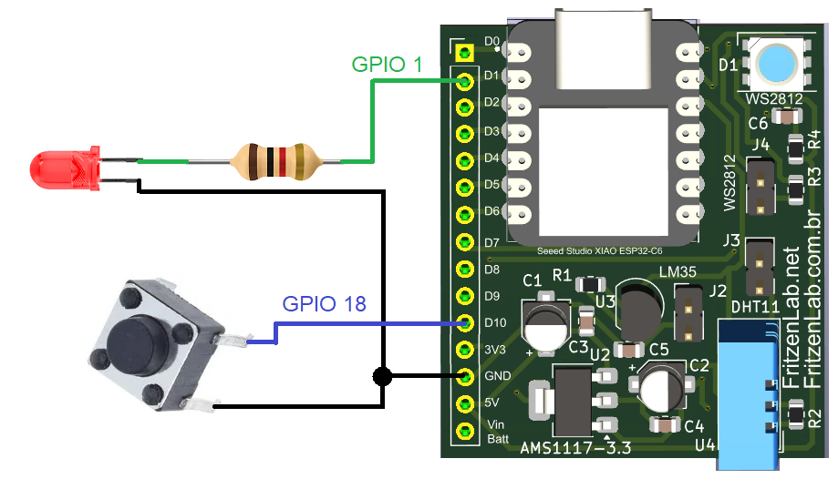
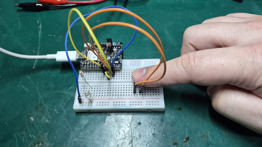
Note that my Xiao ESP32-C6 fits nice with all the circuit in a single 400-point breadboard. That is neat!. There you see the push button on pin GPIO 18 and the LED on GPIO 1.
The code/firmware
Interrupt code for the ESP32 is not so straightforward, specially the ESP-IDF native version I am going to show you. Instead on only using attachInterrupt(), I have to do a couple of steps. These are:
- Configure GPIO, including the input for the push button as interrupt
- Then do:
ESP_ERROR_CHECK(gpio_install_isr_service(0));
    ESP_ERROR_CHECK(gpio_isr_handler_add(BUTTON_GPIO, gpio_isr_handler, NULL));
Then finally call the interrupt function:
// Interrupt Service Routine for the push button
static void IRAM_ATTR gpio_isr_handler(void *arg)
{
    buttonInterrupt = true;
}
As usual with this kind of code, our lopp() could have nothing on it. I say could because it could also have whatever you want to put in it. Full code is below and also in this Github repository.
// Implementation of two LEDs blinking from two separate hardware timers. These are
// general purpose timers "GPTimer0" and "GPTimer1". There is also a push button
// that triggers the watchdog timer. That resets the microcontroller.
#include <driver/gpio.h>
#include <driver/gptimer.h>
#include <esp_task_wdt.h>

#define WDT_TIMEOUT 2 // time in seconds for the watchdog to activate
#define LED_GPIO1 GPIO_NUM_1 // D1 of Xiao ESP32-C6
#define BUTTON_GPIO GPIO_NUM_18 // D10 of Xiao ESP32-C6
gptimer_handle_t led1 = NULL;
volatile bool buttonPressed = false;
static void IRAM_ATTR gpio_isr_handler(void *arg);
volatile bool buttonInterrupt = false;

void setupGPIO()
{
    gpio_config_t io_conf = {};

    // Configure LED1 as output (pin 1 (D1), without pull up or pull down)
    io_conf.mode = GPIO_MODE_OUTPUT;
    io_conf.pin_bit_mask = (1ULL << LED_GPIO1);
    io_conf.pull_up_en = GPIO_PULLUP_DISABLE;
    io_conf.pull_down_en = GPIO_PULLDOWN_DISABLE;
    io_conf.intr_type = GPIO_INTR_DISABLE;
    gpio_config(&io_conf);

    gpio_set_level(LED_GPIO1, 0);

    // Configure button as input (pin 18 (D10) with pull up only)
    // Configure button
    gpio_config_t button_config = {
        .pin_bit_mask = (1ULL << BUTTON_GPIO),
        .mode = GPIO_MODE_INPUT,
        .pull_up_en = GPIO_PULLUP_ENABLE,
        .pull_down_en = GPIO_PULLDOWN_DISABLE,
        .intr_type = GPIO_INTR_NEGEDGE // this says "interrupt on negative edge",
        // All other options are: GPIO_INTR_POSEDGE, GPIO_INTR_NEGEDGE, GPIO_INTR_ANYEDGE, GPIO_INTR_LOW_LEVEL, GPIO_INTR_HIGH_LEVEL
    };
    gpio_config(&button_config);

    ESP_ERROR_CHECK(gpio_install_isr_service(0));
    ESP_ERROR_CHECK(gpio_isr_handler_add(BUTTON_GPIO, gpio_isr_handler, NULL));
}
// Interrupt Service Routine for the push button
static void IRAM_ATTR gpio_isr_handler(void *arg)
{
    buttonInterrupt = true;
}


void setup() {
    setupGPIO();
    esp_task_wdt_config_t wdt_config = {
    .timeout_ms = WDT_TIMEOUT * 1000,
    .idle_core_mask = 0,
    .trigger_panic = true,
};
    esp_err_t err = esp_task_wdt_reconfigure(&wdt_config);
    ESP_ERROR_CHECK(err);
    ESP_ERROR_CHECK(esp_task_wdt_add(NULL));

    setLed1(false);

}

void loop() {
    // when push button on pin 18 (D10 of Xiao ESP32-C6) is pressed
    if (buttonInterrupt)
    {
        buttonPressed= true; // this makes the LED stop blinking and stay solid
        setLed1(true);
    }


    // buttonPressed goes to true when the push button is pressed, effectively
    // preventing the watchdog from being reset periodically. After some time
    // the watchdog is triggered, resetting the microcontroller
    if(buttonPressed == false){

        esp_task_wdt_reset(); // Reset watchdog timer
    }
}
void setLed1(bool state3)
{
    gpio_set_level(LED_GPIO1, state3);
}
Testing our ESP32 hardware interrupt
Copy the code above and paste that into your Arduino IDE. I am using version 2.3.8 but you can run it in any version above 1.8.x. It will just work as intended. Then click the “->” arrow in the top left, called “upload”.
In a couple of seconds the code will start running. I have made it so that it works this way:
- When you press the push button the LED will go ON
- It will stay on for roughly 2 ish seconds, when the watchdog hits and resets the microcontroller,
- then the cycle re-starts, you have to press the push button again.
Remember, if you want to buy the ESP32-C6 used in this experiment, just go to this link of Aliexpress and help me grow the blog. Also if you have any questions, please comment below and also on FritzenLab Youtube.