

Let’s dive in the ESP32 timer interrupt, a way of controlling your programs that is simple and straightforward. We will implement the blink of two LEDs independently, without one interfering on another.
Timers are probably the most basic pheripheral a microcontroller can get. They essentially are able to organize and control timing of everything inside the microcontroller. Even the acclaimed Arduino function called “delay()” is based on the behaviour of a timer.
In fact there is no known way a microcontroller could work without a timer. It is obvious that inputs are the king of of microcontroller, since it is them that will make it act. But timers are essential for things like scheduling and communications, like USB, UART and i2c for instance.
Connecting a timer to an interrupt is even more powerful, since this allows your code to run deterministically. This article is heavily based on the official Espressif documentation for the ESP32. I also had the help of both Claude.ai and ChatGPT to organize my ideas.
My choice for the ESP32 was since I wanted to learn more about it. Then nothing cooler than interrupts to be able to do so. We have talked about interrupts on the ESP32 before. But now I wanted to revisit and expand it, even bringing to you (in future articles) the hardware interrupts and also wathdog. All of the on the ESP32, of course.
ESP32 timer interrupt
So how does it work? there is a couple of steps one has to follow in order to implement a timer interrupt with ESP32. Our exercise today will focus on implementing not one, but two independent timer. I will be using what are called the GPTimer (general purpose timers).
First thing you have to do is to declare a funcion called “createTimer”, or someting similar. It looks just like the one below:
esp_err_t createTimer(
    gptimer_handle_t *timer,
    uint32_t resolution_hz,
    uint64_t alarm_count,
    gptimer_alarm_cb_t callback)
{
    gptimer_config_t config = {
        .clk_src = GPTIMER_CLK_SRC_DEFAULT,
        .direction = GPTIMER_COUNT_UP,
        .resolution_hz = resolution_hz,
    };

    ESP_ERROR_CHECK(gptimer_new_timer(&config, timer));

    gptimer_event_callbacks_t cbs = {
        .on_alarm = callback,
    };

    ESP_ERROR_CHECK(gptimer_register_event_callbacks(*timer, &cbs, NULL));

    gptimer_alarm_config_t alarm = {
        .alarm_count = alarm_count,
        .reload_count = 0,
        .flags = {
            .auto_reload_on_alarm = true,
        },
    };

    ESP_ERROR_CHECK(gptimer_set_alarm_action(*timer, &alarm));
    ESP_ERROR_CHECK(gptimer_enable(*timer));
    ESP_ERROR_CHECK(gptimer_start(*timer));

    return ESP_OK;
}
It contains everything one needs, from callback name and function to error checking and enable/starting flags. That comes before the setup() in Arduino code. Then inside the setup() you actually created the timer as you wish:
createTimer(
    &led1,
    100000,
    20000,
    led1_callback);

    createTimer(
    &led2,
    100000,
    50000,
    led2_callback);
As you can see I created two timers, where:
- 100000 is the timer frequency, in this case 100kHz (that amount to 10uS every “tick”),
- Then the actual timer “time” in terms of the ticks above: so 20000 in the first timer accounts for 200 ms (20000 * 10 uS). As well as 500 mS for the second timer ( 50000 * 10 uS),
- Note that every function has a specific and particular name, “&led1” and “&led2”. Both also feature a specific and particular callback function name.
Then the function IRAM_ATTR is the actual interrupt that will happen:
bool IRAM_ATTR led2_callback(
    gptimer_handle_t led2,
    const gptimer_alarm_event_data_t *edata,
    void *user_ctx)
{
    static bool state = false;
    if(buttonPressed2 == false){
        state = !state;
        gpio_set_level(LED_GPIO2, state);
    }else{
        state = true;
        gpio_set_level(LED_GPIO2, state);
    }

    return false;
}
In here I just flip the “state” of the LED (either true or false) every time the interrupt happens. This is where the magic actually happens, I could put any code here to be executed every “x” micro/mili/seconds.
Hardware
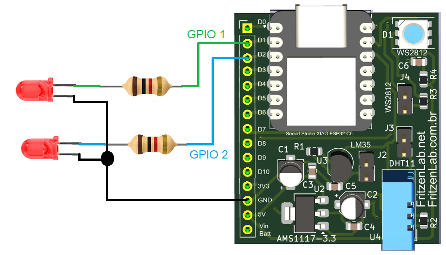
The ESP32 timer interrupt can be tested in a bunch of ways, but I decided to make it simple. All you need for this experiment are two LEDs, one in pin D1 (GPIO 1) and the other in pin D2 (GPIO 2) of the microcontroller. In my case I am using a Xiao ESP32-C6.
I decided for the Xiao uC because I made a circuit board for it (see here). This particular one can be easily used in a small 400-pin breadboard, since it takes up only one pin of each row of the breadboard. Full schematic diagram for this experiment is seen below.
If you want to buy the Xiao ESP32-C6 used in this experiment, please use my Aliexpress link here.
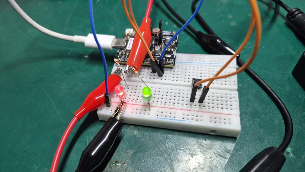
Here is a picture of the experiment assembled on my bench. Notice how small the ESP32-C6 board is, does not even take half the breaboard space.
Firmware/code
As stated above, you need to follow a couple of steps in order to make this timer interrupt code work. You declare the function above setup(), then inside setup() you define the timing you want. I also created a setupGPIO() function to actually not use the likes of digitalWrite(), etc.
void setupGPIO()
{
    gpio_config_t io_conf = {};

    // Configure LED1 as output (pin 1 (D1), without pull up or pull down)
    io_conf.mode = GPIO_MODE_OUTPUT;
    io_conf.pin_bit_mask = (1ULL << LED_GPIO1);
    io_conf.pull_up_en = GPIO_PULLUP_DISABLE;
    io_conf.pull_down_en = GPIO_PULLDOWN_DISABLE;
    io_conf.intr_type = GPIO_INTR_DISABLE;
    gpio_config(&io_conf);

    gpio_set_level(LED_GPIO1, 0);

    // Configure LED2 as output (pin 2 (D2), without pull up or pull down)
    io_conf.mode = GPIO_MODE_OUTPUT;
    io_conf.pin_bit_mask = (1ULL << LED_GPIO2);
    io_conf.pull_up_en = GPIO_PULLUP_DISABLE;
    io_conf.pull_down_en = GPIO_PULLDOWN_DISABLE;
    io_conf.intr_type = GPIO_INTR_DISABLE;
    gpio_config(&io_conf);

    gpio_set_level(LED_GPIO2, 0);

    // Configure button as input (pin 18 (D10) with pull up only)
    io_conf.mode = GPIO_MODE_INPUT;
    io_conf.pin_bit_mask = (1ULL << BUTTON_GPIO);
    io_conf.pull_up_en = GPIO_PULLUP_ENABLE;
    io_conf.pull_down_en = GPIO_PULLDOWN_DISABLE;
    io_conf.intr_type = GPIO_INTR_DISABLE;
    gpio_config(&io_conf);
}
You can see that I also define an input, actually that is the first thing I do. That is for using the watchdog function, which we will not be talking about today. So you don’t need a push button on that input for now.
Same goes for all the code inside loop(), that is all for the watchdog. You can leave the loop() blank if you want. Full code for our experiment is below and also in this GitHub.
// Implementation of two LEDs blinking from two separate hardware timers. These are
// general purpose timers "GPTimer0" and "GPTimer1". There is also a push button
// that triggers the watchdog timer. That resets the microcontroller.
#include <driver/gpio.h>
#include <driver/gptimer.h>
#include <esp_task_wdt.h>

#define WDT_TIMEOUT 2 // time in seconds for the watchdog to activate
#define LED_GPIO1 GPIO_NUM_1 // D1 of Xiao ESP32-C6
#define LED_GPIO2 GPIO_NUM_2 // D2 of Xiao ESP32-C6
#define BUTTON_GPIO GPIO_NUM_18 // D10 of Xiao ESP32-C6
gptimer_handle_t led1 = NULL;
gptimer_handle_t led2 = NULL;
volatile bool buttonPressed1 = false;
volatile bool buttonPressed2 = false;

void setupGPIO()
{
    gpio_config_t io_conf = {};

    // Configure LED1 as output (pin 1 (D1), without pull up or pull down)
    io_conf.mode = GPIO_MODE_OUTPUT;
    io_conf.pin_bit_mask = (1ULL << LED_GPIO1);
    io_conf.pull_up_en = GPIO_PULLUP_DISABLE;
    io_conf.pull_down_en = GPIO_PULLDOWN_DISABLE;
    io_conf.intr_type = GPIO_INTR_DISABLE;
    gpio_config(&io_conf);

    gpio_set_level(LED_GPIO1, 0);

    // Configure LED2 as output (pin 2 (D2), without pull up or pull down)
    io_conf.mode = GPIO_MODE_OUTPUT;
    io_conf.pin_bit_mask = (1ULL << LED_GPIO2);
    io_conf.pull_up_en = GPIO_PULLUP_DISABLE;
    io_conf.pull_down_en = GPIO_PULLDOWN_DISABLE;
    io_conf.intr_type = GPIO_INTR_DISABLE;
    gpio_config(&io_conf);

    gpio_set_level(LED_GPIO2, 0);

    // Configure button as input (pin 18 (D10) with pull up only)
    io_conf.mode = GPIO_MODE_INPUT;
    io_conf.pin_bit_mask = (1ULL << BUTTON_GPIO);
    io_conf.pull_up_en = GPIO_PULLUP_ENABLE;
    io_conf.pull_down_en = GPIO_PULLDOWN_DISABLE;
    io_conf.intr_type = GPIO_INTR_DISABLE;
    gpio_config(&io_conf);
}

esp_err_t createTimer(
    gptimer_handle_t *timer,
    uint32_t resolution_hz,
    uint64_t alarm_count,
    gptimer_alarm_cb_t callback)
{
    gptimer_config_t config = {
        .clk_src = GPTIMER_CLK_SRC_DEFAULT,
        .direction = GPTIMER_COUNT_UP,
        .resolution_hz = resolution_hz,
    };

    ESP_ERROR_CHECK(gptimer_new_timer(&config, timer));

    gptimer_event_callbacks_t cbs = {
        .on_alarm = callback,
    };

    ESP_ERROR_CHECK(gptimer_register_event_callbacks(*timer, &cbs, NULL));

    gptimer_alarm_config_t alarm = {
        .alarm_count = alarm_count,
        .reload_count = 0,
        .flags = {
            .auto_reload_on_alarm = true,
        },
    };

    ESP_ERROR_CHECK(gptimer_set_alarm_action(*timer, &alarm));
    ESP_ERROR_CHECK(gptimer_enable(*timer));
    ESP_ERROR_CHECK(gptimer_start(*timer));

    return ESP_OK;
}

bool IRAM_ATTR led1_callback(
    gptimer_handle_t led1,
    const gptimer_alarm_event_data_t *edata,
    void *user_ctx)
{
    static bool state = false;
    if(buttonPressed1 == false){
        state = !state;
        gpio_set_level(LED_GPIO1, state);
    }else{
        state = true;
        gpio_set_level(LED_GPIO1, state);
    }

    return false;
}
bool IRAM_ATTR led2_callback(
    gptimer_handle_t led2,
    const gptimer_alarm_event_data_t *edata,
    void *user_ctx)
{
    static bool state = false;
    if(buttonPressed2 == false){
        state = !state;
        gpio_set_level(LED_GPIO2, state);
    }else{
        state = true;
        gpio_set_level(LED_GPIO2, state);
    }

    return false;
}
void setup() {
    setupGPIO();
    esp_task_wdt_config_t wdt_config = {
    .timeout_ms = WDT_TIMEOUT * 1000,
    .idle_core_mask = 0,
    .trigger_panic = true,
};
    //Serial.begin(115200);
    esp_err_t err = esp_task_wdt_reconfigure(&wdt_config);
    //Serial.println(esp_err_to_name(err));
    ESP_ERROR_CHECK(err);
    ESP_ERROR_CHECK(esp_task_wdt_add(NULL));
    createTimer(
    &led1,
    100000,
    20000,
    led1_callback);

    createTimer(
    &led2,
    100000,
    50000,
    led2_callback);
}

void loop() {
    // when push button on pin 18 (D10 of Xiao ESP32-C6) is pressed
    if (gpio_get_level(BUTTON_GPIO) == 0)
    {
        buttonPressed1= true; // this makes the LED stop blinking and stay solid
        buttonPressed2= true; // this makes the LED stop blinking and stay solid
    }
    // buttonPressed goes to true when the push button is pressed, effectively
    // preventing the watchdog from being reset periodically. After some time
    // the watchdog is triggered, resetting the microcontroller
    if(buttonPressed1 == false && buttonPressed2 == false){
        esp_task_wdt_reset(); // Reset watchdog timer
    }
}
Testing and end result
Copy the code above and paste that into your Arduino IDE. I am using version 2.3.8 but you can use any version above 1.8.x, you will be fine. Then Press the “->” arrow in the top left, already with the ESP32-C6 connected to the computer via USB cable.
After a couple of seconds both LEDs will blink, one at 2.5Hz and the other at 1Hz. I made a video explaining all of that to you, it is in the top of this article, enjoy. Also, please comment below or on Youtube if you have any questions.
Pingback: ESP32 hardware interrupt the easy way - FritzenLab electronics