
I made a Pomodoro timer with PIC12F675, using MPLAB X and XC8 compiler. It times between 15 and 60 minutes at the press of a button. Also known as egg timer, it has four presets: 15, 30, 45 and 60 minutes.
The official page for this project is here.
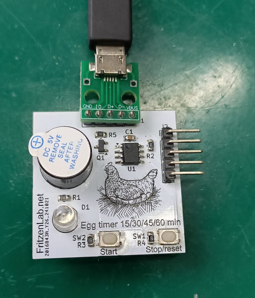
The idea is to have a small electronic product to aid my studies, allowing me to focus for a period (pomodoro technique). Then when the pomodoro timer goes off, I can rest for a bit before coming back to studying. See a picture of the project below.
How does it work?
But how does it work? plug it into any USB port for power; Now press the “Start” button between one and four times in sequence (not so quick, not so slow). After the first button press you have a total of 4 seconds to press the button up to 3 more times. Wait a couple of seconds and the buzzer will sound and the LED will light the number of times you pressed the button.
So if you pressed the button once, the LED will glow once and the buzzer will buzz once. And so on, up to four times. This is how the button presses will affect the time being counted:
- Pressing “Start” once will allow for a 15 minutes time
- Pressing “Start” twice will allow for 30 minutes time
- Pressing “Start” three times will allow for 45 minutes time
- Finally pressing the “Start” four times will allow for 60 minutes time.
Just a quick heads up: this project was made in Kicad 8 and MPLAB X 6.20 (with PICkit3 and XC8). For these old PIC microcontrollers (like the PIC12F675) and PICkit3, you MUST use MPLAB X 6.20. Newer versions won’t support PICkit3 anymore. All project files (PCB, code) are on this Github, enjoy.
For stoping this timer mid-counting there is the “Stop” button, just press it once and the PIC will reset itself using the watchdog. After counting have started there is no effect in pressing the “Start” button again, nothing will happen. There is no time extension as well, so either you press the “Stop” button and start over, or wait for the timer to finish its counting.
Hardware/circuit board
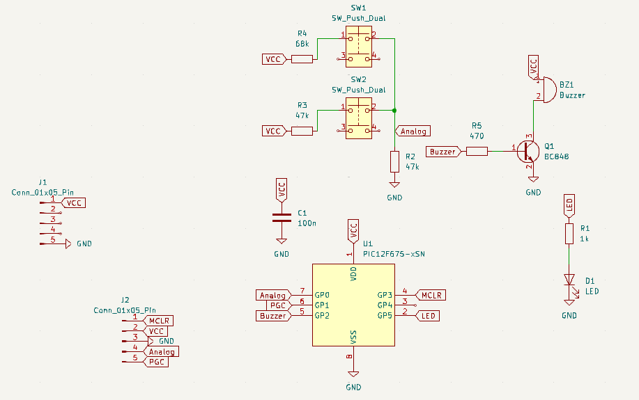
Circuit for this product is very basic, our PIC12F675 in SOIC8 is supplied with 5V straight from a micro USB port. There is a transistor driving the active buzzer and one LED being directly driven by the PIC. The coolest trick lies on the push buttons: they are both connected to a single analog input of the PIC.
Pressing either one of the push buttons will create a resistor divider with a fixed 47k Ohm resistor. Such resistor divider will allow an analog input of the PIC to capture different values, depending on the push button pressed.
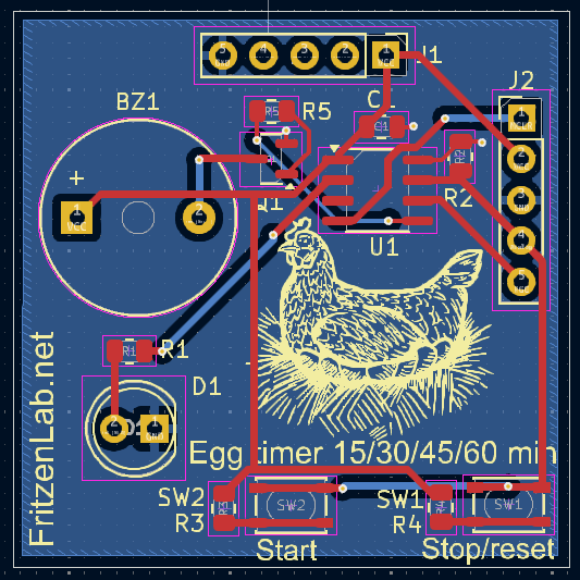
Circuit board was made using Kicad 8 and its standard libraries. I sent it to fabrication in JLCPCB for cheap. Then finally hand-soldered all components and tested it in my bench.
Project execution
I am not a professional PIC programmer or anything. Despite working with embedded systems, my day job is more related to hardware. But as a good maker in my free time I can program STM32’s, PIC, Arduino and a bunch of other systems. I picked a PIC microcontroller for this project due to its simplicity to wire and program.
Also that is due to its low cost and high availability in my country (Brazil) even when compared to Attiny85. For cost alone I could have used those cheap CH32 from Aliexpress, would do the job. But still I went with PIC due to being easier to find references online for. Speaking of references, I used mainly these three: timer, interrupt, ADC.
Also of course I wrote this article in August/2025 so got a bunch of help (and wrong answers) from ChatGPT and Gemini. During this project I figure that, due to the current state of A.I’s, what I had to do was to be careful. I had to direct the A.I and give it clear instructions with the smallest pieces of information possible. Just this way anything useful came out of it.
Firmware/code
Now talking about code, everyhing you need is here, in a folder called “egg-timer-2.X”. Also the official page for this project is this. I had to learn a bunch of concepts in order to complete this project: timers, interrupts, analog to digital converters, moving average algorithm. You can see ADC readings below, it is a small function:
unsigned int Read_Adc(void) {
    ADCON0bits.GO_nDONE = 1;          // Start A/D conversion
    while (ADCON0bits.GO_nDONE);      // Wait for conversion to complete
    // Return full 10-bit result (ADRESH is 8-bit, ADRESL is 2-bit, shifted to form 10-bit)
    return ((unsigned int)ADRESH << 8) | ADRESL;
}
I created an one milisecond interrupt, where I have all the counters to keep track of things on the main loop. Nothing on my code is blocking, I don’t have a single “for()” (ok, I have an empty one, inside the main loop), I don’t use delays. Everything is based on timers and using variables to count time on top of those 1ms.
I had to ChatGPT the moving average algorithm, necessary to smooth out the push button pressing analog readings. Before implementing it, my button presses would sometimes not go through or sometimes be ghost ones. I do one analog reading every 20ms and the buttons click tracks every 300ms.
Testing it out
I have not really kept track of every single timing execution on the code on this Pomodoro timer with PIC12F675. I did not verify whether 300ms really live up to that or not. But what I cound verify, which was the final counting time (15 to 60 minutes) was that for example the longest time (60 minutes, 3600 seconds) took 3611 seconds.
Not bad for a crystal-less unprocessed/unfiltered voltage (5V straight from USB) microcontroller project. Testing this device is straightforward, as you can see in the video below. You will plug it into any USB port (could be your laptop’s, power bank, etc) then press the “Start” button as many times you want (up to four). Pressing the “Stop” button at this time does nothing.