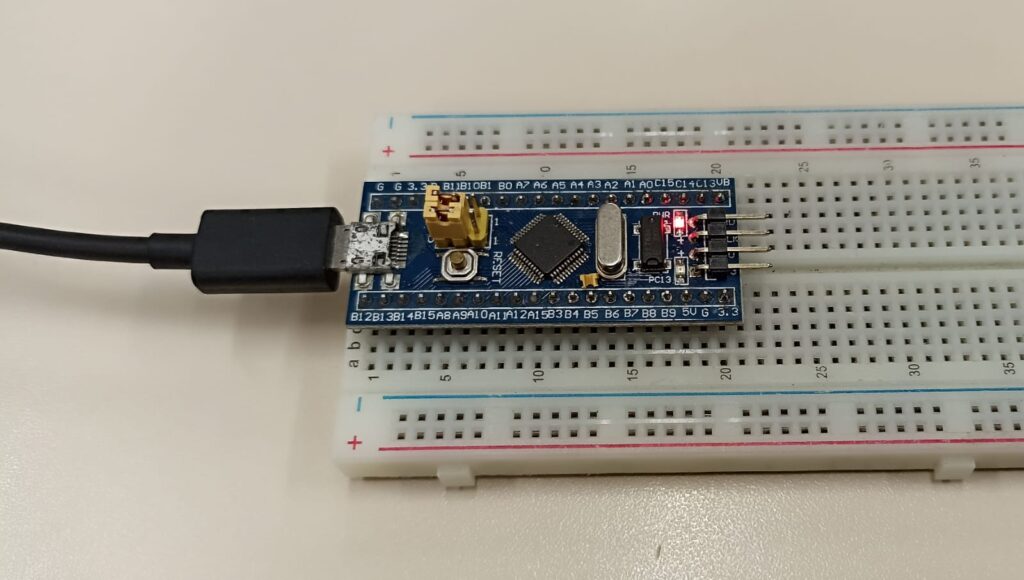
You may have already heard or read about using the STM32 blue pill with Arduino. This small board is based on the STM32F103C8T6 microcontroller from ST Semiconductors, with the following specifications:
- ARM Cortex-M3
- 12kBytes of programming memory (Flash)
- 20kBytes SRAM memory
- 3 Timers
- 2x SPI, 2x I2C
- 3 USART, 1 CAN
- 1 USB
- 37 GPIO
- Analog to digital converter: 2x 10 channels
- 72MHz operating frequency
- Supply voltagem between 2V and 3.6V
In terms of consumption and resources, it is a microcontroller far superior to Arduino’s ATMEGA328. Its price makes it attractive to directly replace similar microcontrollers, combined with the fact that it can also be programmed via the Arduino IDE.
How to make it Arduino compatible?
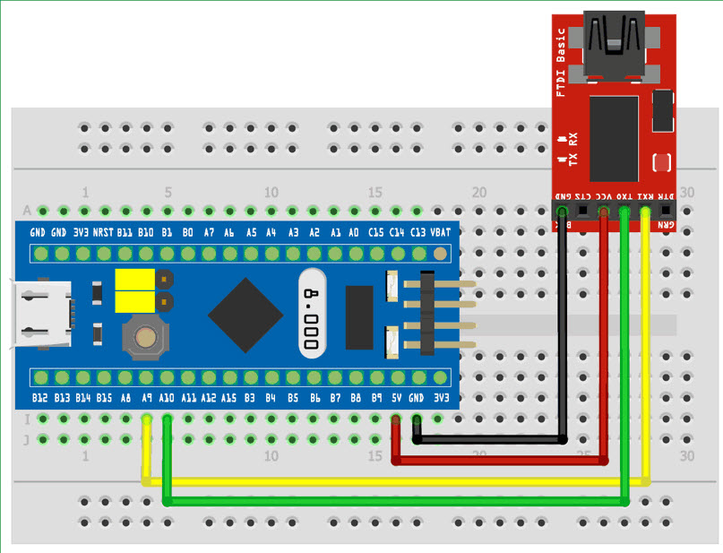
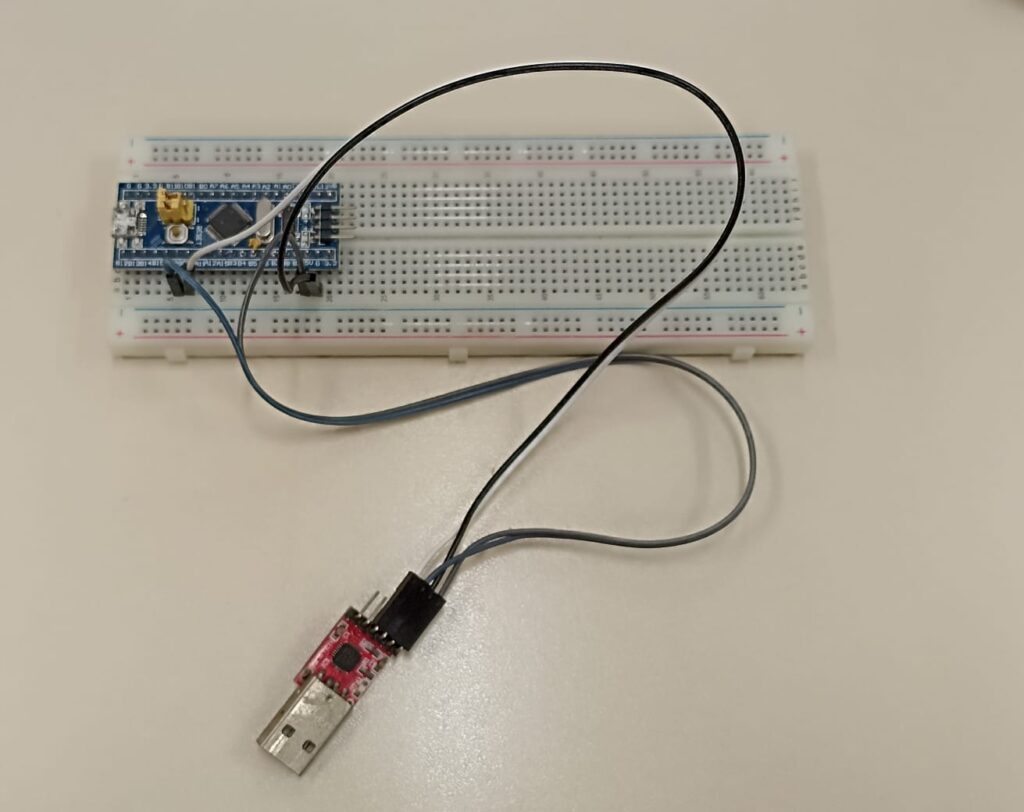
The procedure I followed came from this link. You will need any USB-serial converter, in addition to the STM32CubeProgrammer software, downloadable here (you have to register for free). Assemble the circuit below.
Before opening STM32CubeProgrammer, download the “generic_boot20_pc13.bin” binary available here. This is the bootloader, code that makes the STM32 blue pill able to be programmed via the Arduino IDE.
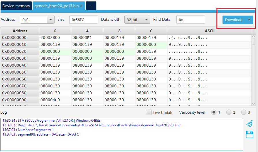
When opening the STM32CubeProgrammer, select “open file” and search the computer for the file “generic_boot20_pc13.bin”. On the right select “UART” and click “Connect”.
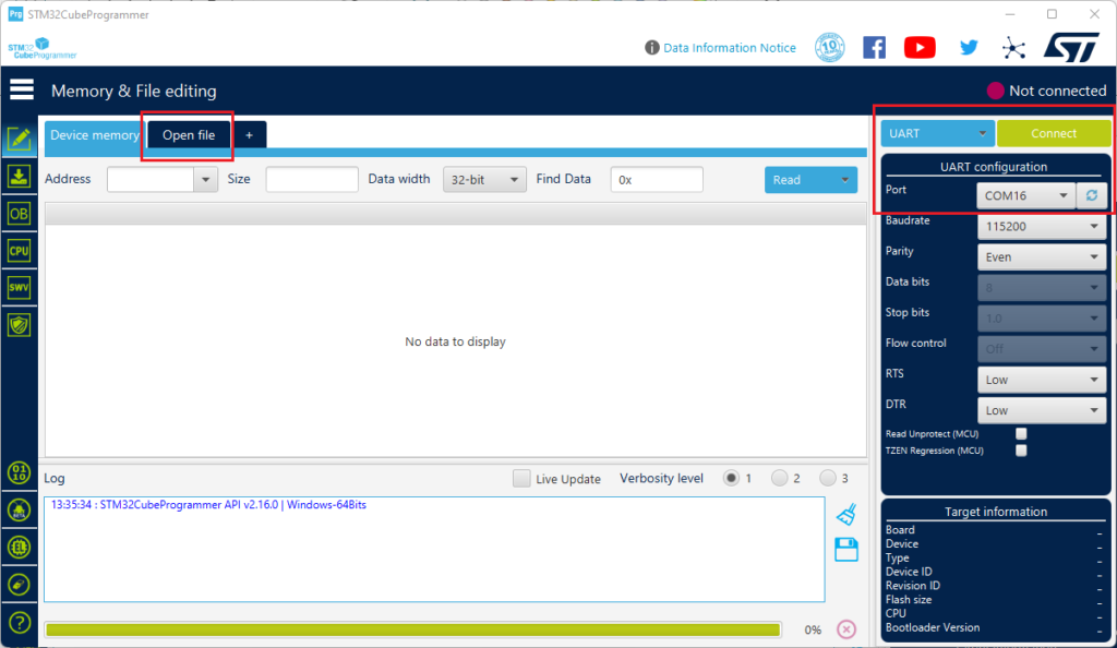
Then click on “Download” on the right and wait for the flashing to finish.
Configuring the Arduino IDE
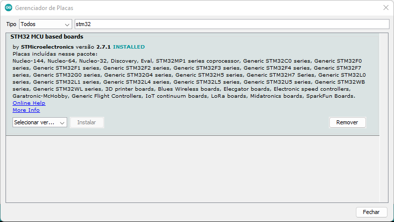
Considering that you already have the Arduino IDE software installed, following this procedure, perform the steps below. Copy the link provided below and paste it into “File > Preferences > Additional URLs for Board Managers:”
https://github.com/stm32duino/BoardManagerFiles/raw/main/package_stmicroelectronics_index.jsonGo to “Tools > Board > Boards Manager” and type “STM32”, the library to be installed is this:
You need to install a USB driver as mentioned in this link. It is available here. The penultimate step is to configure the options for the connected board, in “Tools” menu as shown in the image below.
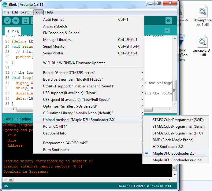
The most important settings are: “Board: Generic STM32F1 series”, “U(S)ART support: enabled” and “Upload method: Maple DFU Bootloader 2.0”.
The code
The last step to be able to write codes on the board is to write a sketch that uses the serial port, it could be the sketch below. I found out about it at this link. Set the BOOT1 jumper to 1 and leave BOOT0 to 0. At this point you can remove the USB-serial converter and connect a USB cable directly to the blue pill.
// constants won't change. Used here to set a pin number:
const int ledPin =  PC13;// the number of the LED pin

// Variables will change:
int ledState = LOW;             // ledState used to set the LED

// Generally, you should use "unsigned long" for variables that hold time
// The value will quickly become too large for an int to store
unsigned long previousMillis = 0;        // will store last time LED was updated

// constants won't change:
const long interval = 500;           // interval at which to blink (milliseconds)

void setup() {
  // set the digital pin as output:
  pinMode(ledPin, OUTPUT);
  Serial.begin(115200);
}

void loop() {
  // here is where you'd put code that needs to be running all the time.

  // check to see if it's time to blink the LED; that is, if the difference
  // between the current time and last time you blinked the LED is bigger than
  // the interval at which you want to blink the LED.
  unsigned long currentMillis = millis();

  if (currentMillis - previousMillis >= interval) {
    // save the last time you blinked the LED
    previousMillis = currentMillis;

    // if the LED is off turn it on and vice-versa:
    if (ledState == LOW) {
      ledState = HIGH;
    } else {
      ledState = LOW;
      Serial.print("teste");
    }

    // set the LED with the ledState of the variable:
    digitalWrite(ledPin, ledState);
  }
}
You only need to do this (write a code with the serial port with BOOT1 set to 1) once. After carrying out this procedure, return the BOOT1 jumper to 0.
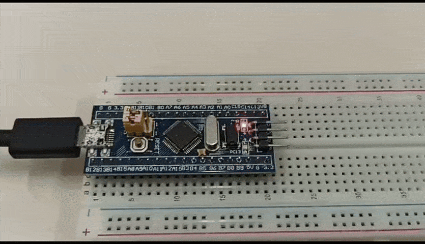
Finally, with both jumpers on the board at 0, just write code in the Arduino IDE and press the “-> Load” button. In the gif below I am running the famous “BlinkWithoutDelay” sketch. Note that the blue pill onboard LED pin name is “PC13”.
Final considerations
Do you want to purchase a Blue pill STM32F103? buy here. This board has a very interesting appeal due to its high power and low cost, in addition to being able to be programmed using the Arduino IDE.
Also, please check my article about the STM32C0 with STM32Cube IDE. In the future I plan to bring more articles about the blue pill and the STM32C0.


Pingback: Programming STM32 Bluepill with Arduino IDE - FritzenLab electronics