This page is dedicated to my PIC12F675 Pomodoro study timer (or egg timer), featuring one LED, two push buttons and one active buzzer. I have programmed it in C using MPLAB X IDE 6.20, which is one of the last to support Pickit3 programmer.
Pomodoro is a technique used for studying/concentration/focus where you concentrate for a period of time, then make small pauses.The objective of my Pomodoro timer is for you to select a time by pressing a button (between 15, 30, 45 or 60 minutes); Then an LED will turn on and stay that way until time passed.
Then finally at the end of the Pomodoro time the buzzer will beep for three seconds and the LED will go off. You can stop the count at any given time by pressing the second push button. It will zero the microcontrollers variables. Buttons are both connected to a single pin, configured as analog input.
There is a 5-pin connector for the Pickit3 and another for a micro-USB circuit board, for power supply. So you can use this Pomodoro timer connected to any (even cheaper ones) USB cellphone charger. In this page you will find everything necessary to repricate the product: from schematic diagram, PCB layout and C code. Along with pictures and videos of the Pomodoro timer working.
Interfaces
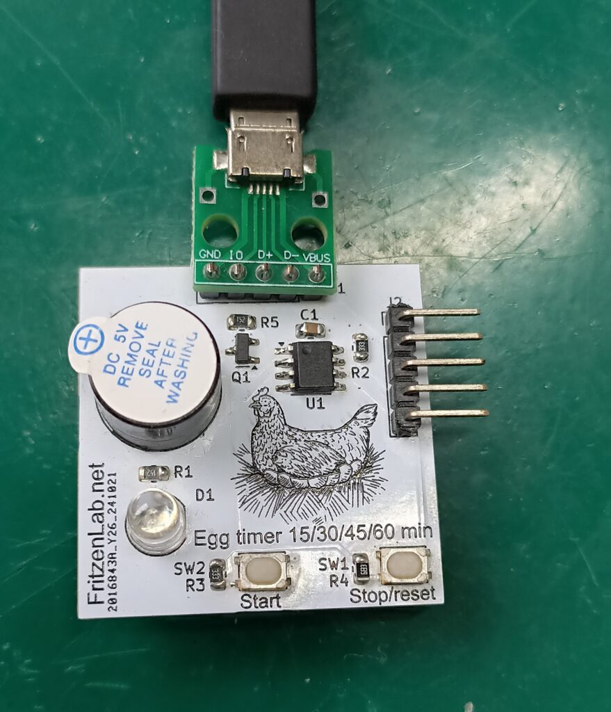
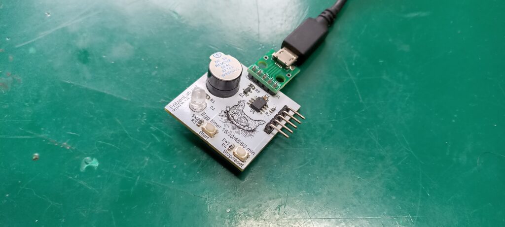
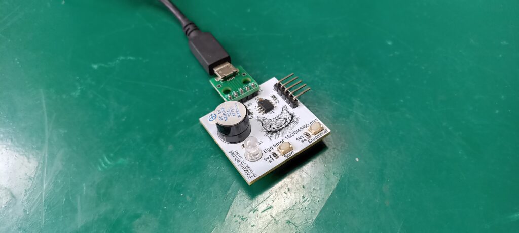
Picture above shows it all, everything there is to this product. On the top there is a small green board, which provides 5V to our design from a micro-USB connector. Any small cellphone charger will work with this Pomodoro timer. To the right there is the 5-pin connector for programming with Pickit3.
On the left side are two things: the active buzzer for sound and one LED (D1) for visuals. Then finally there are two push buttons connected to a single analog input, for start and stop. Also of course there is the drawing of a chicken on the board, it does not work without it.
How does it work?
When you power the board up, nothing happens, no LED and now buzzer. In order for it to start timing, you must press the start button up to four times within 4.6 seconds. This is the time it allows you to select a time, from the first button press up to the last. There are four available times to select from: 1 press for 15 minutes, 2 presses for 30 minutes, 3 presses to 45 minutes and finally 4 presses to 60 minutes.
After you pressed the start button up to four times within 4.6 seconds, the LED will blink and the buzzer will buzz that number of times. So for example if you pressed the button 3 times, the LED will blink and the buzzer will buzz 3 times. Time counting will start immediately, with the LED staying ON for the whole time.
Time will pass accordingly, then at the end of the counting the LED will remain on and the buzzer will buzz for 3 seconds. After that both (LED and buzzer) go off for good, until the next press of buttons. But say you want to restart or stop the count in the middle, what do you do? you briefly press the Stop push button.
GIF above shows me pressing the Start button four times, then the LED takes its time and blinks four times as well. Then it will remain on for the remainder of the counting time.
Schematic diagram and PCB layout
Before going any further, please note that every file necessary for this project (schematic diagram, PCB layout, pictures, C code) is stored in this Github, enjoy. I used Kicad 8 software for schematic diagram capture and printed circuit board layout. Printed circuit board size turned out to be 34x34mm, so small and cute. The only downside of this small dimension is that the USB cable dictates the position of the board.
Our PIC12F675 is supplied directly from the USB 5V, featuring a 100nF capacitor for decoupling. LED D1 is turn ON and OFF also directly from the PIC12F GP5 pin. Buzzer is driven by a transistor, which is connected to pin GP5 of our PIC12F. Resistor divider for the push buttons turned out to be a bit different from the picture below. It is actually a 33k Ohm resistor to GND and a 33k Ohm resistor for the Start button and a 68k Ohm resistor for Stop button.
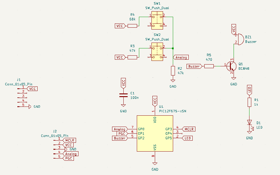
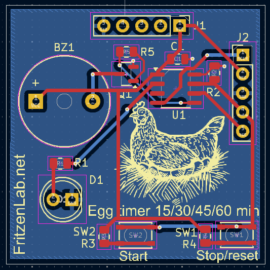
PIC12F675 I used comes in SOIC-8 SMD configuration, so a bit of caution soldering it is advisable. Same applies for both push buttons, they are SMD and very heat-sensitive. All traces are 20mil (0.5mm) width, neither too thin nor too thick. LED is a 5mm TH one for ease of sight.
Firmware/code
As stated before, all code was made in C in MPLAB X IDE, using XC8 as a compiler. It is available here for you to use. I consulted a couple of sources to come up with my final code. Those are all in the header of the “main.c” file. Google Gemini also helped me refine the code.
Voltages measured in the prototype for the Stop and Start button press are: Stop 0.32V (65 of 1023) and Start 0.64V (130 of 1023), in a 0-1023 scale. So those values are the ones used in the code to detect button presses in an analog way. Coming from Arduino I had to learn a bit of everything to make my code. Primarily I had to make a timer interrupt work (which I did) and also analog readings (which I did).
After I got a good handle of those topics, the “rest” was simple C logic, IF’s and the such. So much so that I am already thinking of porting my PIC12F code to Arduino any time soon. Below I paste the interrup (ISR) part of the code, NOT THE COMPLETE CODE, which you can get here.
void __interrupt() ISR() {
    // Check if Timer0 interrupt flag is set

    if (T0IF) {

        // Timer0 is configured to interrupt every 1ms (250kHz / 250 increments = 1kHz)
        // TMR0 is reloaded with 6 (256-250) to achieve 250 counts per interrupt
        ledtimer++;
        buttonstimer++;
        adtimer++;

        // Main timer logic: increments counttime if starttimer is active
        if (starttimer == 1) {
            counttime++;
            // Check if the main timer has reached its final quantity
            if ((finalquantity - counttime) < 1) {
                counttime = 0;     // Reset the main timer counter
                longtimecounter++;
                if(longtimecounter >= 144){ // 30seg * 2= 1min, 2* 60min = 120 (1.2 * 120 = )
                    finalquantity = 0; // Mark final quantity as reached
                    starttimer = 0;    // Stop the main timer
                    // If a process was started, activate the final buzzer
                if (processstarted == 1) {
                    finalbuzzer = 1;      // Activate the final buzzer sequence
                    processstarted = 0;   // Reset process started flag after triggering buzzer
                }
                }


            }
        }

        // Logic for the final buzzer sequence
        if (finalbuzzer == 1) {
            finalbuzzercounter++;
            canstartblinking = 0; // Stop LED blinking during buzzer sound
            if (finalbuzzercounter <= 3000) { // Buzzer active for 3 seconds (3000ms)
                buzzeron = 1;
            } else {
                buzzeron = 0;                 // Turn buzzer off
                // Reset all flags and counters to prepare for a new cycle
                starttimer = 1;               // Re-enable timer for next sequence (if needed, or set to 0 if full reset)
                                              // NOTE: Setting starttimer=1 here will immediately start counting again.
                                              // Consider if you want it to wait for a new button press.
                                              // If you want it to wait, set starttimer=0 here.
                processbuttonclicks = 0;
                processstarted = 0;
                finalbuzzercounter = 0;
                finalbuzzer = 0;

            }
        }

        // LED blinking logic during button click processing
        if (ledtimer >= 200 && processbuttonclicks > 0 && canstartblinking == 1) {
            processbuttonclicks--; // Decrement the blinking count
            if (start == 1) {
                start = 0; // Toggle LED state
                buzzeron = 0;
            } else {
                start = 1;
                buzzeron= 1;
            }
            ledtimer = 0; // Reset LED timer
        } else if (processbuttonclicks <= 0 && canstartblinking == 1) {
            // Once blinking is done, set the final quantity based on button clicks
            if (timecontrol == 4) {
                finalquantity = 30000; // 30 seconds
            } else if (timecontrol == 3) {
                finalquantity = 22500; // 22.5 seconds
            } else if (timecontrol == 2) {
                finalquantity = 15000; // 15 seconds
            } else if (timecontrol == 1) {
                finalquantity = 7500; // 7.5 seconds
            } else {
                finalquantity = 0; // Default to 2 seconds
            }
            // After setting final quantity, if not already started, start the main timer
            if (starttimer == 0 && finalbuzzer == 0) { // Ensure buzzer isn't active
                starttimer = 1; // Start the main timer countdown
                canstartblinking = 0; // Stop blinking after time is set
            }
        }

        // Control LED and Buzzer output based on state
        if ((start == 1 && starttimer == 0) || (starttimer == 1 && finalquantity != 0) || buzzeron == 1) {
            // LED is ON if blinking (start==1 and starttimer==0), or main timer is running, or buzzer is on
            LED = 1;
            // Buzzer is ON only if it's the final buzzer sequence
            if (buzzeron == 1) {
                BUZZER = 1;
            } else {
                BUZZER = 0; // Ensure buzzer is off if not in final buzzer state
            }
        } else {
            // LED is OFF if not blinking, main timer is finished, or buzzer is off
            LED = 0;
            BUZZER = 0; // Ensure buzzer is off
        }

        T0IF = 0; // Clear Timer0 interrupt flag
        TMR0 = 6; // Reload Timer0 to achieve 1ms interrupt (256 - 250 = 6)
    }
}
Final product timing is firstly defined as four different delays: 7.5, 15, 22.5 and 30 seconds. Those delays are then executed 144 times to come to 15, 30, 45 and 60 minutes. The actual multiplier is supposed to be 120, not 144. But in my experience 120 times gave delays 16% below the targeted 15/30/45/60 minutes. This is most likely due to inaccuracies in the PIC12F675 internal clock.
Since this is a low cost and recreative product, it is ok to “adjust” timing like I did. But of course in a real hardware you would use a crystal oscillation or a better microcontroller.