Let’s work with buttons on analog pins, with a device that reads ten buttons using just one analog input from any microcontroller. The idea is to save microcontroller pins, such as the Attiny85, which only has 6 pins available.
I do this using a resistive divider, where each button pressed “closes” the circuit with a resistor of a different value. This makes it possible to obtain different voltages by pressing different buttons.
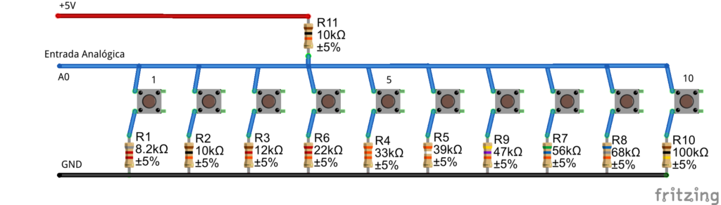
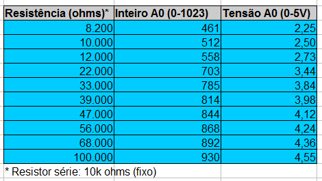
The voltage in the image is 5V, but 3.3V can be used. See that we have a 10k resistor at the high end and the following resistors at the low end: 8k2, 10k, 12k, 22k, 33k, 39k, 47k, 56k, 68k, 100k. Below you see the integer values obtained on the Arduino UNO for each resistor, as well as the respective voltage.
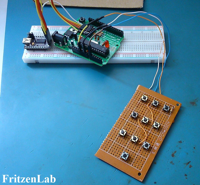
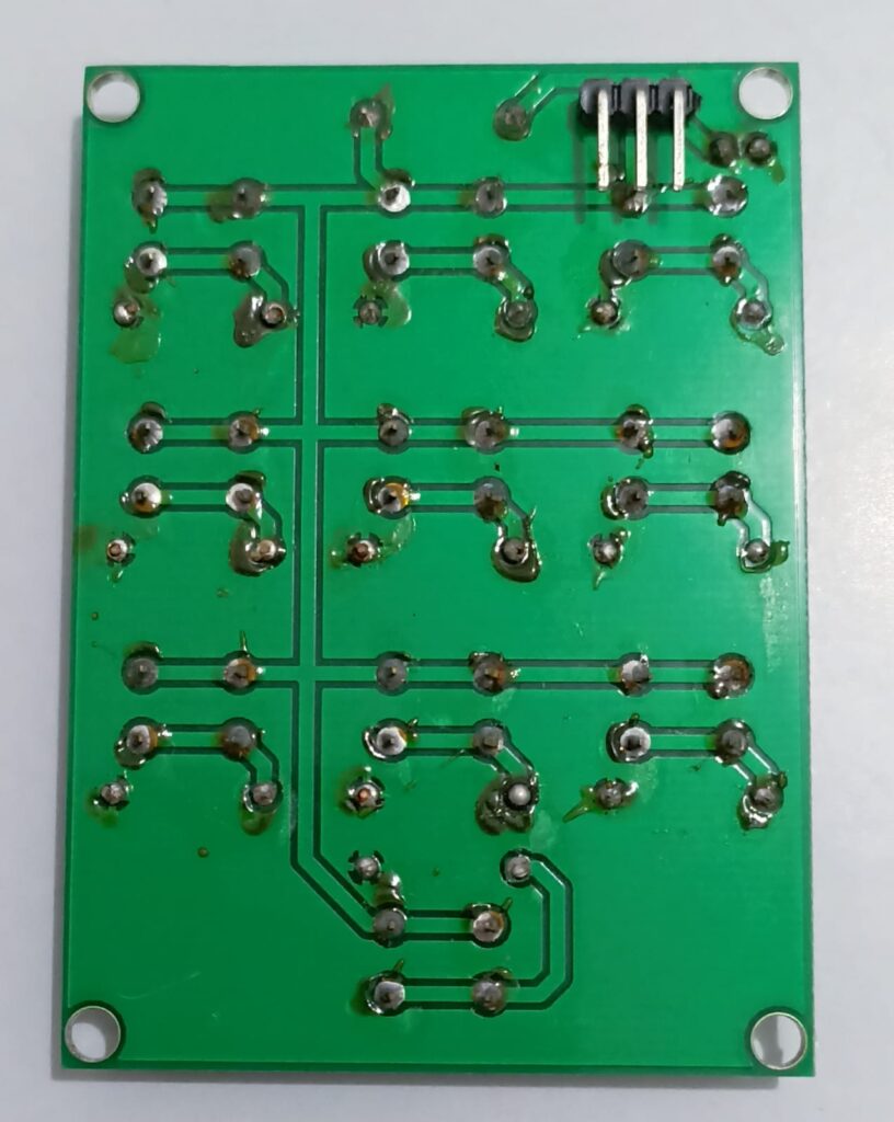
In our case of 10 buttons, the voltage values were very far from each other, any analog-to-digital converter can read them. I made a prototype of the circuit on a perforated board, with the “final” components. In the test below I am using the Fritzen UM, an Arduino that I made myself.
I then created a printed circuit board for the project, as seen below. I placed a 100nF capacitor at the analog voltage output, for filtering.
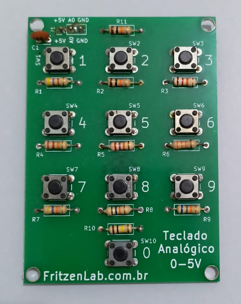
All board manufacturing files (in Kicad) are here.
Testing
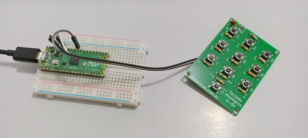
In order to test the product’s operation, I created a code for Arduino, at this link. I also created code for microPython on the Raspberry Pi Pico, which has a 16-bit response (65535 values). The Circuit is seen below: the analog pin is 26, other than that just put 3.3V and GND on the board.
In terms of code It is very simple, I just read the entire value (analog representation) in
pot_value = pot.read_u16()and I send it to print on the serial port, every 100mS.
# Complete project details at https://RandomNerdTutorials.com/raspberry-pi-pico-analog-inputs-micropython/
from machine import Pin, ADC
from time import sleep

pot = ADC(Pin(26))

while True:
  pot_value = pot.read_u16() # read value, 0-65535 across voltage range 0.0v - 3.3v
  print(pot_value)
  sleep(0.1)
Remembering that to work with microPython on the Raspberry Pi Pico I use the Thonny IDE, whose configuration guide is here. The result appears in the Thonny IDE shell/console, seen below.
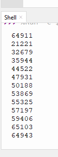
See that the value 21221 is button one, 32679 is button two and so on, until you reach 59406 which is button zero (see keyboard image above). The first and last values of the image (64911 and 64943) are for no button pressed (full scale).
These values can then be processed, for example through IF() to perform the function you want.
To wrap up
The idea of using an analog input to read different buttons is not new, there are plenty of references on the internet. It’s a great “tool” to have in your everyday toolbox. If you want to purchase the circuit board, comment below or get in touch via my LinkdeIn.


