The idea is to make a Bicycle speedometer with ESP-12 (ESP8266MOD), a chip that would allow us to create an app to verify the bicycle speed. I plan to measure the speed of the bicycle in km/h (kilometers per hour) using a reed switch sensor and a magnet on the wheel.
This is just like any other bicycle speedometer works basically. The difference in my project will be the display (there will not be a proper display): I will show the speed in six LEDs in increments of 5km/h. So LED 1 is >5km/h, LED 2 is >10km/h and LED 6 is >30km/h. This means that I cannot measure precisely anything above 30km/h, which for a weekend leisure bicycle is ok in my opinion.
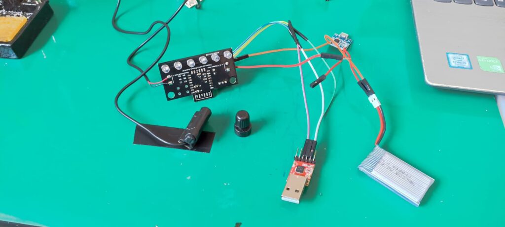
As previously stated I will be using an ESP8266 ESP-12 as the brains of the project, just because I have a bunch of them laying around. The connections of it for programming and reseting will be fairly similar to the ones found here.
State of the project
The project is finished, tested and ready for you to use it (and buy from me if you want. Just send me a message at the end of the page). I have shared a bunch of project updates: check all of them here.
The schematic diagram and layout
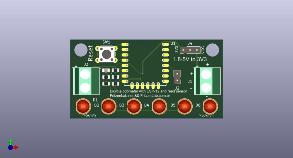
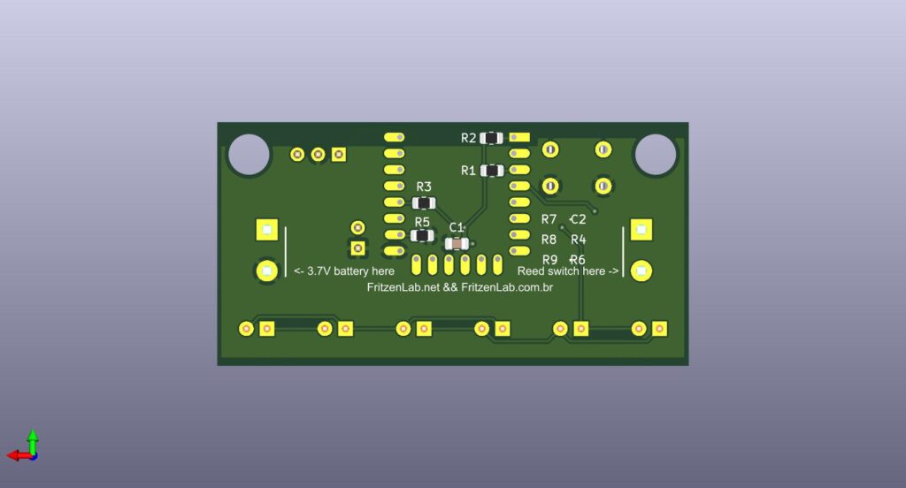
Speaking of connections, here is the schematic diagram and printed circuit board layout of the project. It is all avaible on my Github, here.
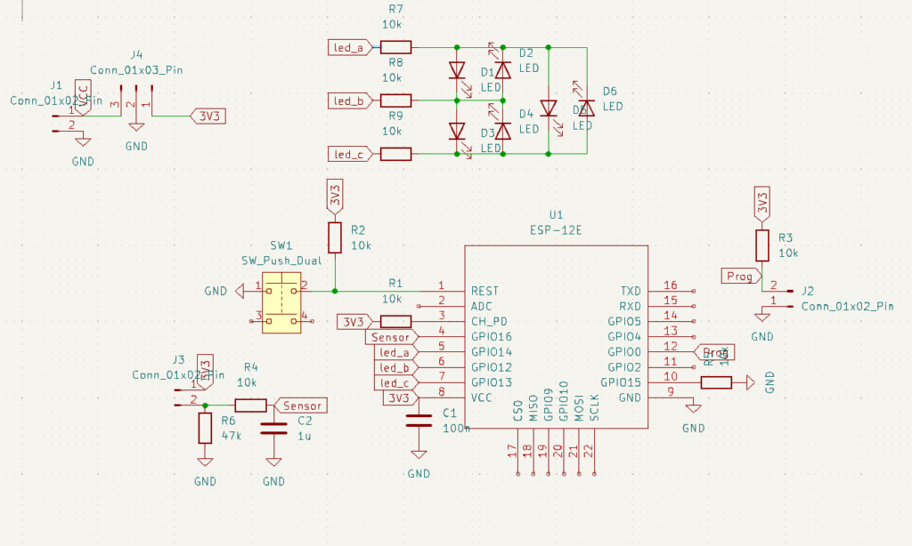
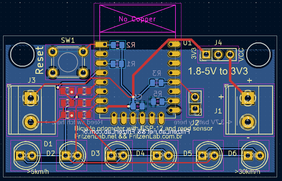
A couple of things to notice: the six LEDs will be charlieplexed, using only three pins of the ESP-12. There is a 2.54mm jumper for entering the ESP-12 programming mode. The reed switch input goes through a RC circuit for low pass filtering.
After testing and validating the design, I changed C2 from 1uF to 100nF. There is a three-pin connector for the voltage regulator, whose discussion will follow.
The voltage regulator
I initially considered using the AMS1117-3.3 LDO (low drop output) voltage regulator, but according to its datasheet it has a drop voltage of 1.1V. I want to use Lithium 3.7V batteries in this project so a 1.1V drop in 3.7V would be down to 2.6V, not enough for the ESP-12 to function.
There are other commonly available LDOs around, but all of the are 0.6V or higher of drop voltage. Not enough. I then considered using buck converters, putting the voltage down from 3.7V. That has problems too, since a low battery voltage (say 3.5V or lower) would make it not viable for the buck to generate the required 3.3V.
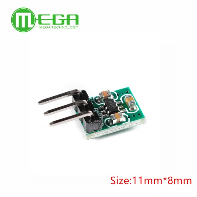
I ended ep settling for a buck-boost circuit (actually a charge pump) called HX4002 from Aliexpress, enough for what I need. It goes up to 150mA with voltages between 2.7V and 5.5V.
Project characteristics in bullet points
- ESP-12 WiFi chip controller.
- Reed switch speed sensor (same as any other bicycle speedometer).
- 3.3V Buck-boost (charge pump) regulator for 3.7V Lithium battery supply, with TP4056 for charging.
- The “display” of speed will be six 5mm green LEDs.
- There is a reset push button and a programming jumper for the ESP-12. I did not assemble it in the prototype.
- I plan to add WiFi capabilities in the future, maybe for an APP or webpage to be able to read speeds.
The code
As stated, the microcontrolled used in this project is a ESP8266MOD (ESP12 anyone?). All I need from it are four pins: one of the reed sensor switch and three for the charlieplexed LEDs. There is no HMI (human machine interface), no adjusts, no nothing. The bicycle wheel perimeter is hard-coded into it.
Sensor activation detection is made using a edge detection algorithm: there is a varible for the previous state and there is digitalRead() for the current state. If the previous state was zero (false) and the digitalRead() returns one (true) then an rising edge was detected. That’s all I need, my code works from there.
Also there is a RC low pass filter as debounce in hardware, so the signal comes in very clean. This made it unnecessary to implement any filtering or debounce in software. LED charlieplexing is done as usual, unused output is set as an input and there you go.
// First thing, install the ESP8266 support on the Arduino IDE,
// with a link from here https://blog.eletrogate.com/nodemcu-esp12-usando-arduino-ide-2/

// board pinout for Wemos D1 https://forum.arduino.cc/t/weird-wemos-d1-r1/920394/29?page=2
// board pinout for NodeMCU V3 https://cyberblogspot.com/nodemcu-v3-esp8266-pinout-and-configuration/

#include <ESP8266WiFi.h> // just to turn WiFi off, info from here https://arduino.stackexchange.com/questions/43376/can-the-wifi-on-esp8266-be-disabled

// for light sleep woken by a GPIO, I used this reference https://efcomputer.net.au/blog/esp8266-light-sleep-mode/
// there is also something here https://kevinstadler.github.io/notes/esp8266-deep-sleep-light-sleep-arduino/

#define led_a 14 // charlieplex pin 1
#define led_b 12 // charlieplex pin 2
#define led_c 13 // charlieplex pin 3
#define sensor 16 // reed sensor

// Required for LIGHT_SLEEP_T delay mode
/*extern "C" {
  #include "user_interface.h"
  #include "gpio.h"
}*/

long currenttime;
long oldtime;
int sleepcounter;
bool previoussensorstatus;
long timeelapsed;
long previoustime;
float speedms;
float speedkmh;
float wheelperimeter= 2.0 * 3.14159265 * 0.365; // perimeter= 2 * pi * radius
int calldisplaycounter;
int requiredled;
int zerospeedcounter;
int callserialprint;
int contador;

/*void light_sleep(){
   wifi_station_disconnect();
   wifi_set_opmode_current(NULL_MODE);
   wifi_fpm_set_sleep_type(LIGHT_SLEEP_T); // set sleep type, the above    posters wifi_set_sleep_type() didnt seem to work for me although it did let me compile and upload with no errors
   wifi_fpm_open(); // Enables force sleep
   gpio_pin_wakeup_enable(GPIO_ID_PIN(4), GPIO_PIN_INTR_HILEVEL); // GPIO_ID_PIN(2) corresponds to GPIO2 on ESP8266-01 , GPIO_PIN_INTR_HILEVEL for a logic HIGH, can also do other interrupts, see gpio.h above
   //gpio_pin_wakeup_enable(4, GPIO_PIN_INTR_HILEVEL);
   wifi_fpm_do_sleep(0xFFFFFFF); // Sleep for longest possible time
 }*/

void ledon(int requiredled){
  //Serial.println("entrei");
  switch (requiredled) {
  case 0:
    pinMode(led_a, INPUT);
    pinMode(led_b, INPUT);
    pinMode(led_c, INPUT);
    //digitalWrite(led_a, LOW);
    //digitalWrite(led_b, LOW);
    //digitalWrite(led_c, LOW);
    break;
  case 1:
    pinMode(led_a, OUTPUT);
    pinMode(led_b, OUTPUT);
    pinMode(led_c, INPUT);
    digitalWrite(led_a, HIGH);
    digitalWrite(led_b, LOW);
    //digitalWrite(led_c, LOW);
    break;
  case 2:
    pinMode(led_a, OUTPUT);
    pinMode(led_b, OUTPUT);
    pinMode(led_c, INPUT);
    digitalWrite(led_a, LOW);
    digitalWrite(led_b, HIGH);
    //digitalWrite(led_c, LOW);
    break;
  case 3:
    pinMode(led_a, INPUT);
    pinMode(led_b, OUTPUT);
    pinMode(led_c, OUTPUT);
    //digitalWrite(led_a, LOW);
    digitalWrite(led_b, HIGH);
    digitalWrite(led_c, LOW);
    break;
  case 4:
    pinMode(led_a, INPUT);
    pinMode(led_b, OUTPUT);
    pinMode(led_c, OUTPUT);
    //digitalWrite(led_a, LOW);
    digitalWrite(led_b, LOW);
    digitalWrite(led_c, HIGH);
    break;
  case 5:
    pinMode(led_a, OUTPUT);
    pinMode(led_b, INPUT);
    pinMode(led_c, OUTPUT);
    digitalWrite(led_a, HIGH);
    //digitalWrite(led_b, LOW);
    digitalWrite(led_c, LOW);
    break;
  case 6:
    pinMode(led_a, OUTPUT);
    pinMode(led_b, INPUT);
    pinMode(led_c, OUTPUT);
    digitalWrite(led_a, LOW);
    //digitalWrite(led_b, LOW);
    digitalWrite(led_c, HIGH);
    break;
  default:
    // comando(s)
    break;
}
}
void setup() {
  // put your setup code here, to run once:
  Serial.begin(9600);

  WiFiMode(WIFI_STA);
  WiFi.disconnect();
  WiFi.mode(WIFI_OFF);
  WiFi.forceSleepBegin();
  delay(100);

  pinMode(sensor, INPUT);
  //gpio_init();

}

void loop() {
  // put your main code here, to run repeatedly:

  currenttime= micros();
  if(currenttime - oldtime > 5000){ //verifies the sensor every 5ms
    oldtime= micros(); // after 5ms have passed, reset the time counter
    zerospeedcounter++;
    if(zerospeedcounter > 600){ // if more than three seconds have passed without sensor detection (less than an avarage of 3km/h)
      speedkmh= 0; // zero the speed variables
      speedms= 0;
      timeelapsed= 0; // zero the last elapsed time
    }
    if(digitalRead(sensor) && !previoussensorstatus){ // if sensor is HIGH and just was LOW
      zerospeedcounter= 0; // if the sensor was detected within 3 seconds, zero the zero speed flag
      timeelapsed= millis() - previoustime; // calculates the elapsed time between now and the last sensor state change
      speedms= wheelperimeter / (timeelapsed / 1000.0); // THIS calculates speed, wheel perimeter over time elapsed between sensor detections. Dividing by 1000 to get seconds
      speedkmh= speedms * 3.6; // converts m/s to km/h and rounds it for displaying
      previoustime= millis(); // reset the previoustime variable to the current millis()
      previoussensorstatus= true; // when the sensor goes to HIGH this variables goes too
    }else if(!digitalRead(sensor) && previoussensorstatus){ // if sensor is LOW and just was HIGH
      previoussensorstatus= false; // when the sensor goes LOW, reset this variable
    }
    // function to call and light the LED display
    calldisplaycounter++;
    if(calldisplaycounter == 50){ // every 250ms
      calldisplaycounter= 0;

      if(speedkmh >= 30){
        ledon(6);
      }else if(speedkmh >= 25){
        ledon(5);
      }else if(speedkmh >= 20){
        ledon(4);
      }else if(speedkmh>= 15){
        ledon(3);
      }else if(speedkmh >= 10){
        ledon(2);
      }else if(speedkmh >= 5){
        ledon(1);
      }else{
        ledon(0);
      }
    }
    /*callserialprint++;
    if(callserialprint == 100){
      callserialprint= 0;
      Serial.println(timeelapsed);
    }*/
  }
}
A future work in software is to put the entire ESP8266MOD to sleep between the 5ms detection windows, in order to save a bunch of miliamps from being wasted.
The assembly
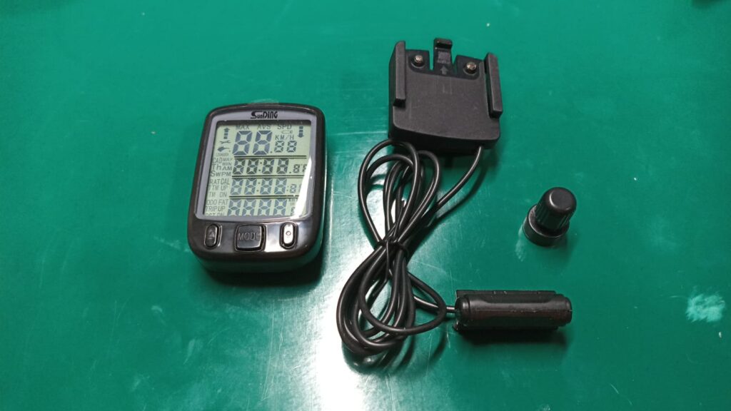
I went after the reed sensor and magnet for the project. I found that they would cost more if bought specifically for that (like replacement parts) than if I bought a complete odometer kit. So I got a cheap US$7 bicycle odometer kit just to salvage parts.
Here are pictures of the assembled printed circuit board.
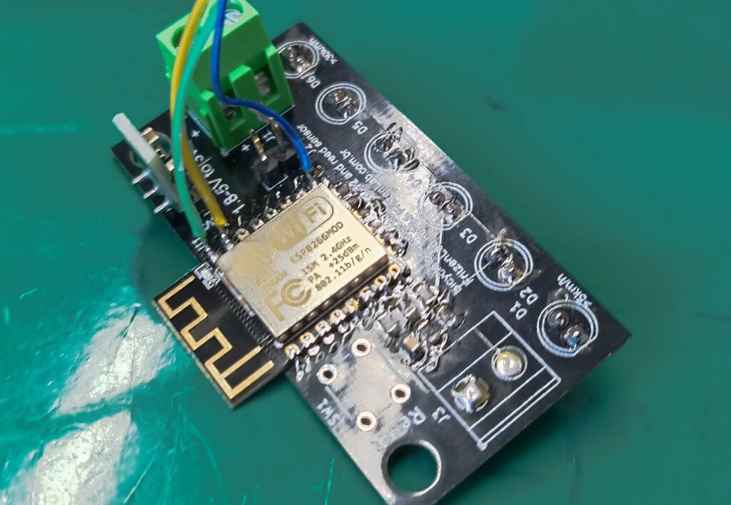
This is the “backside” where everything will stay, except the six LEDs that will be facing outside the box. Also notice the three wires soldered to the ESP8266MOD: they are the RX, TX and GND for programming. I forgot to add a connector to it.
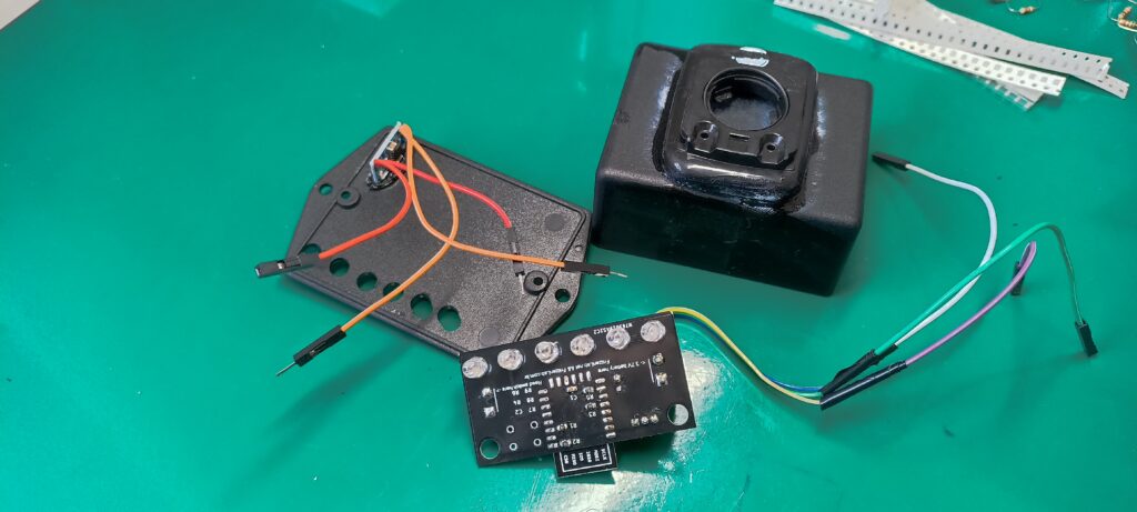
in the picture above there are quite a few details. Notice the box cover with six holes for the LEDs, also the TP4056 battery charger box attached to it. Here you can see the “front side” of the PCB with the six LEDs and a couple of resistors. There is also the box whose back is glued to the backside of a commercial odometer, for railing it into the bicycle.
Final product
After a couple of hours programming and assembling, it is time to test the Speedometer out. You can see below it attached to my bicycle; notice the detachable green connector for the reed switch sensor. It allows for me to remove the box and carry it with me.
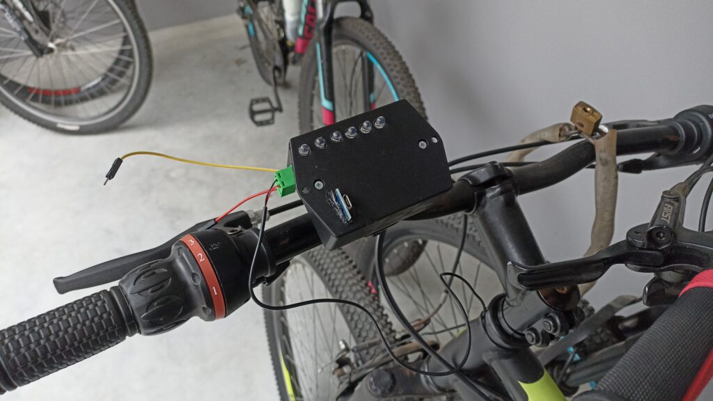
There are two wires coming out of the box. These are the (+) battery connections, so that I can remove power from the speedometer. I should have bought a proper switch (may in the future). Below is a video of the system working, me riding my bicycle. You will probably see no LEDs lit but I assure you they were.
Future work
As seen in the project updates linked above, the power consumption of the chip in “bicycle stopped” state is around 70mA. It is very high for the 400mAh LiPo battery I am using, you cannot leave it idling for long. I originally intended to make GPIO16 (the same used for the reed sensor reading) to “wake up” the ESP8266MOD when the bicycle startes moving.
I then read about it further and figured that GPIO16 acts like an ouput in this case, resetting the ESP’s reset pin. So no using GPIO16 to wake it up for me. Another option which I am thinkering about right now is to put the chip to deep sleep, but I don’t really see how to wake it up when necessary.
To finish and leave you thinkering about this project, remeber that all project files (Kicad, pictures) are in my Github.


")

