
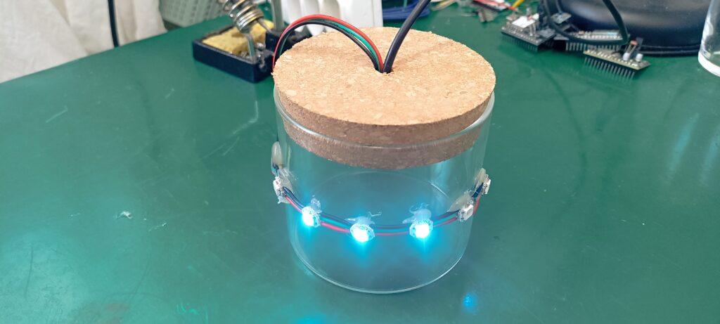
We will implement a decorative WiFi binary thermometer, using WS2812b LEDs and an ESP32. Temperature in degrees Celsius will be shown in binary format in six RGB addressable LEDs.
The idea is to implement a thermometer for environment temperature, relying on an online service called OpenWeatherMap. Our ESP32-C3 Super Mini will consult such online service every fifteen (15) minutes. It will ask for temperature in my city in degrees Celsius. If for any reason the WiFi does not connect or the service does not answer, we have a backup.
I have attached an LM35 temperature sensor to analog pin 4 (A4) of the ESP32-C3. So if and when the “online” OpenWeatherMap temperature is not available, we can just read our local analog sensor.
Binary display
I love using binary notation as display for things, as seen here and here before. The whole idea is to exercise your mind, since you have to convert from binary to decimal every time. In our case there will be six WS2812b LEDs, since 2^6 = 64.
That number is more than enough to represent decimals in degrees Celsius. A temperature of 100 degrees Fahrenheit is around 37-38 degrees Celsius. The way binary display work is like this (see image):
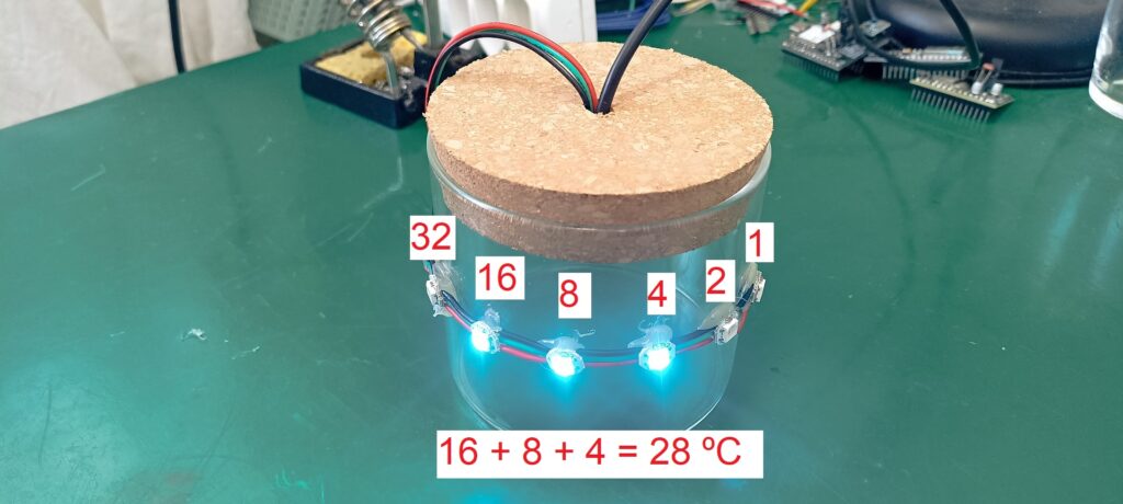
Every LED has a “weight”, where the most significative weights 32, the next 16 and so on, up until the last which represets 1 in decimal. So in the image above the LEDs 16, 8 and 4 are ON, getting us 16 + 8 + 4 = 28 ºC.
Our LEDs of choice (WS2812b) are addressable and RGB, meaning they are controlled by a single pin of the ESP32-C3. In our case that is GPIO 3, but it could virtually be any other pin.
Hardware
Today’s post hardware is divided in three main parts: the microcontroller which is the ESP32-C3 Super Mini, the temperature sensor which is the LM35. And finally the LEDs, which are 6x WS2812b. To supply the project with 5V I have savaged an USB cable.
I have striped the “other” end and soldered it directly to the ESP32-C3 board. The USB-A end of such cable can be plugged to any USB port, since the LEDs current is not that high at all. In case you ever need to update firmware on the ESP32, please connect a USB-C cable to the board itself.
Schematic diagram is seen below, along with a picture of the assembly. I have actually hot-glued everything in place, just like in a quick prototype. Sensor LM35 goes to GPIO 4 while the WS2812b’s go to GPIO 3.
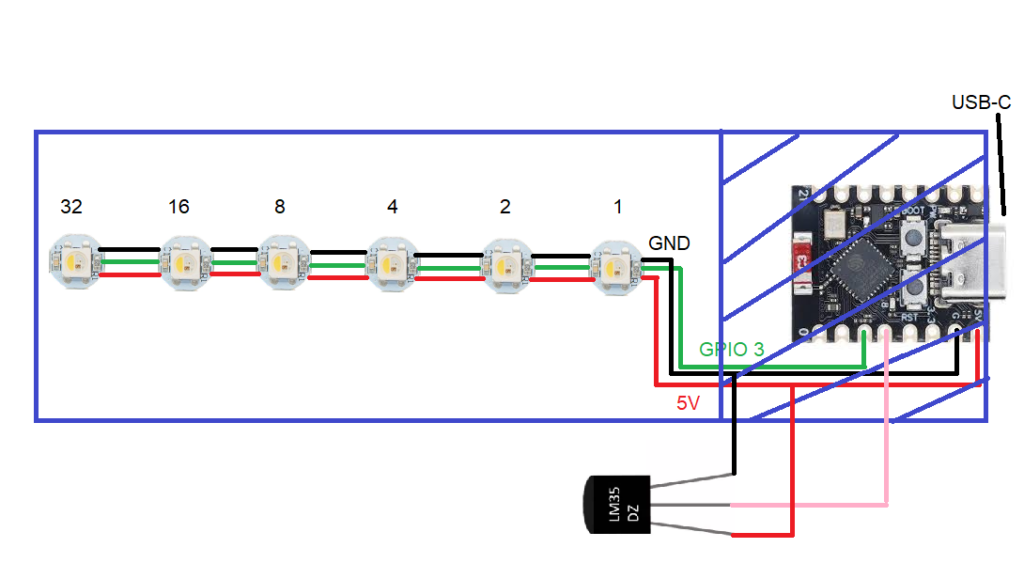
As stated before, power supply is not pictured above but it is just an USB cable with its user-end connector cut out and soldered directly to the ESP32-C3 Super Mini board.
Coding/firmware
I made this code using Arduino IDE 2.3.7, but have also compiled and downloaded it to the board using the online Arduino IDE. That was just to make sure it would really compile anywhere. Since I made it modular and using functions, the main() is very short, take a look.
void loop() {

  readTemperature(); // read temperature, either from the internet or from an LM35
  // First, try to fix WiFi if it's broken
  ensureWiFi();
  if(newValueAvailable == true){ // if there is a new temperature reading available,
    getRandomColor(); // pick a random color to apply to the WS2812b's
    turnLEDsON(); // turn ON LEDs in color and sequence pre-defined
    newValueAvailable= false; // after updating the LEDs, zero the flag to wait for new readings
  }

}
I execute the readTemperature() very often, but inside it there is a time protection, making it only really execute every 15 minutes. I also verify often whether there is a new temperature value available, using the tag “newValueAvailable”.
If and when there is a new value avaible, I randomly decide the color the LEDs will assume in the next 15 minutes. Then I do my magic to convert an integer (temperature) into binary, to decide which LEDs will go on this time. I have actually taught you to do just that in this post.
So to summarize everything that has to be done for this project to work:
- Try to fetch temperature data from OpenWeatherMap, if not
- Read the LM35 analog sensor
- When done obtaining the temperature value, convert it to binary
- Then decide randomly which color the LEDs will assume for the next 15 minutes
- Finally turn the LEDs on, taking into account which LEDs should go up and at which color.
Full code
Full code is seen below and also in my Github.
 // https://openweathermap.org/ to get your API KEY
 // WS2812b neopixels: https://fritzenlab.net/2024/07/14/ws2812b-addressable-rgb-led-with-esp32-c6/
 // Generate true random numbers with ESP32: https://fritzenlab.net/2025/12/06/generate-random-numbers-with-esp32/
#include <WiFi.h>
#include <HTTPClient.h>
#include <ArduinoJson.h> // Parsing JSON from OpenWeatherMap

#define lm35_PIN 4 // Use GPIO 4 (A4)

#include <Adafruit_NeoPixel.h>
#define D_in 3
#define qtdeLeds 6
Adafruit_NeoPixel pixels(qtdeLeds, D_in);

#include <esp_system.h> // Required for esp_random()

float temp = 0;
unsigned long updateTimer = 0;
bool gotTemperature = false;
int intTemp= 0;
int bitsToTurnON[6]= {0}; // Here lives the information of which LEDs WS2812b will turn ON at any given time
bool newValueAvailable= false; // flag to the pixels that a new temperature is available
uint32_t red, green, blue= 0;
bool firstPass= true;

const char* ssid     = "";
const char* password = "";
String apiKey        = "";
String city          = "";
String countryCode   = "BR";

void setup() {
  Serial.begin(115200);
  analogReadResolution(12);

  WiFi.begin(ssid, password);
  Serial.print("Connecting to WiFi");
  while (WiFi.status() != WL_CONNECTED) {
    delay(500);
    Serial.print(".");
  }
  Serial.println("\nConnected!");

  pinMode(D_in, OUTPUT);      //Configura o pino 6 como saída
  pixels.begin();             //Inicia o objeto "pixels"
  updateTimer= millis();
}

void loop() {

  readTemperature(); // read temperature, either from the internet or from an LM35

  if(newValueAvailable == true){ // if there is a new temperature reading available,
    getRandomColor(); // pick a random color to apply to the WS2812b's
    turnLEDsON(); // turn ON LEDs in color and sequence pre-defined
    newValueAvailable= false; // after updating the LEDs, zero the flag to wait for new readings
  }

}

bool getTemperatureOnline() {
  if (WiFi.status() != WL_CONNECTED) {
    return false; // Don't try if WiFi is down
  }

  HTTPClient http;
  String serverPath = "http://api.openweathermap.org/data/2.5/weather?q=" + city + "," + countryCode + "&APPID=" + apiKey + "&units=metric";

  http.begin(serverPath);
  int httpResponseCode = http.GET();

  if (httpResponseCode == 200) {
    String payload = http.getString();
    DynamicJsonDocument doc(1024);
    deserializeJson(doc, payload);

    temp = doc["main"]["temp"];
    temp = round(temp);
    //Serial.print("Online Temp Found: ");
    http.end();
    return true;
  } else {
    Serial.print("HTTP Error: ");
    Serial.println(httpResponseCode);
    http.end();
    return false;
  }
}

void getTemperatureOffline() {
  float sumSensor = 0;
  // Reduced delay from 5000ms to 50ms so the serial monitor actually responds
  for (int i = 0; i < 10; i++) {
    sumSensor += analogRead(lm35_PIN);
    delay(50);
  }

  float averageADC = sumSensor / 10.0;
  // ESP32 LM35 Calculation: (ADC_Value * Reference_Voltage / Max_ADC_Steps) / 10mv per degree
  float milliVolts = (averageADC * 3300.0) / 4095.0;
  temp = round(milliVolts / 10.0);

  Serial.print("Offline (LM35) Temp: ");
}
void readTemperature(){
  if (((millis() - updateTimer) > 900000) || firstPass == true) {
    updateTimer = millis();

    //Serial.println("\n--- Attempting Update ---");
    // First, try to fix WiFi if it's broken
    ensureWiFi();

    if (!getTemperatureOnline()) {
      Serial.println("Online failed. Switching to LM35...");
      getTemperatureOffline();
    }

    intTemp= int(temp);
    Serial.println(temp);
    convertToBinary(); // convert the integer of temperature in degrees Celsius to binary
    newValueAvailable= true; // flag to the pixels that a new value is available
    firstPass= false;
  }
}
void convertToBinary() {
  int value = int(round(temp));

  for (int led = 0; led < qtdeLeds; led++) {
    int bitIndex = (qtdeLeds - 1) - led;  // MSB on LED 0
    bitsToTurnON[led] = bitRead(value, bitIndex);
  }

  // Debug print (MSB → LSB)
  for (int i = 0; i < qtdeLeds; i++) {
    Serial.print(bitsToTurnON[i]);
  }
  Serial.println();
}

void turnLEDsON(){
  pixels.clear(); // start by clearing all pixels
  for(int i = 0; i < 6; i++){ // iterate within the 6 WS2812b (5 downto 0)
    if(bitsToTurnON[i] == 1){ // if current pixel was marked as 1 (ON)
      pixels.setPixelColor(i, pixels.Color(red, green, blue)); // apply color
    }
  }
  pixels.show(); // after defining color for all pixels, turn them ON
}
void getRandomColor(){
  red = randomRange(10, 253);
  green = randomRange(10, 253);
  blue = randomRange(10, 253);

int zeroSome= randomRange(1,4);
  if(zeroSome == 1){
    red= 0;
  }else if(zeroSome == 2){
    green= 0;
  }else if(zeroSome == 3){
    blue= 0;
  }
}

// Returns a random number in the range [0, bound)
// Avoids modulo bias using rejection sampling
uint32_t randomBounded(uint32_t bound) {
  if (bound == 0) return 0;  // avoid division by zero

  uint32_t x;
  uint32_t limit = UINT32_MAX - (UINT32_MAX % bound);

  do {
    x = esp_random();
  } while (x >= limit);  // Retry until unbiased

  return x % bound;
}

// Returns a random number in the range [minVal, maxVal)
uint32_t randomRange(uint32_t minVal, uint32_t maxVal) {
  if (maxVal <= minVal) return minVal;
  return minVal + randomBounded(maxVal - minVal);
}
bool ensureWiFi() {
  int attempts = 0;
  const int maxAttempts = 5;

  if (WiFi.status() == WL_CONNECTED) {
    return true;
  }

  Serial.println("\nWiFi disconnected. Attempting to reconnect...");
  WiFi.disconnect(); // Clear existing failed states
  WiFi.begin(ssid, password);

  while (WiFi.status() != WL_CONNECTED && attempts < maxAttempts) {
    delay(2000); // Wait 2 seconds per attempt
    attempts++;
    Serial.print("Retry ");
    Serial.print(attempts);
    Serial.println("/5...");
  }

  if (WiFi.status() == WL_CONNECTED) {
    Serial.println("Reconnected successfully!");
    return true;
  } else {
    Serial.println("WiFi reconnection failed.");
    return false;
  }
}
A couple of things have to be taken into account for this to work: insert your WiFi network alias and password; go to https://openweathermap.org/ and obtain your ApiKey. This is free but has its limits. I have seen recommendations online to keep the requests at 15+ minutes apart. That is to be on the safe side and not be banned.
Also please select your city and country. The city must exist and be available into the OpenWeatherMap network. If you do not find your city pick one nearby. I have not made anything special to the LM35 reading, just an average of 10 readings.
What you could do if the readings jump too much is add a 10uF capacitor between its output and ground (GND). But hopefully you are always going to have a WiFi connection, so the LM35 readings will never need to be used.
One thing I did to the code later, after finishing the project was to improve the randomized color picking. I noticed that just randomly asking for RGB numbers between 0 and 255 would not give me strong, well defined colors. Instead it would alway present a white background and then some blue, pink, yellow, green.
What I did was I always zero one of the colors, right after it is picked randomly. So effectively always one color is OFF an the other two are ON. That brings strong yellows, pinks and red, green, blue color every time. I accomplished that with the code below.
int zeroSome= randomRange(1,4);
  if(zeroSome == 1){
    red= 0;
  }else if(zeroSome == 2){
    green= 0;
  }else if(zeroSome == 3){
    blue= 0;
  }
Result and final words
Copy the code above and paste it into your Arduino IDE. Then add your WiFi credentials, you OpenWeatherMap ApiKey, city and country. Finally connect your ESP32-C3 to your computer via USB-C cable and hit “upload”. That is in the Arduino IDE, a green arrow located in the top left corner of the software.
After a couple of seconds, which is the time it takes for the WiFi to connect, you will see the LEDs turn ON. If not, please check that you typed your WiFi credentials correctly, as well as the ApiKey, city and country. You could totally add more (there is some) Serial.print() messages to check what is happening.
I made a video to explain how the project works, see the beginning of the article. Please feel free to watch it and comment your questions on Youtube, if necessary. Also if you want to buy the LEDs used in this tutorial, go to my Aliexpress link here.