
Let us learn how to read and control the ESP32-C3 internal temperature sensor with Arduino code. Most (but not all) ESP32 microcontrollers feature an internal temperature sensor. Today’s subject, ESP32-C3 Super mini, also has one.
UPDATE: same code of this post applies to the newer ESP32-C5 as well
We have explored that before with MicroPython, in this post, have a look. When it comes to internal temperature sensors, often times they serve a very noble purpose. That is to offer a glimpse on the thermal load that the code execution generates.
It basically means they can help us control the processing load, by means of checking whether the microcontroller is too hot or stressed. One can also obtain a “picture” of the environment temperature around the microcontroller, after of course executing a minimal calibration.
A bunch of microcontrollers feature such internal sensor, since it is often only comprised of a diode. That component’s PN junction voltage is highly dependent on its surrounding temperature. These are often precise enough that no calibration is needed, at least for the application.
Also space inside a chip for a couple more transistors and diodes is not a huge problem, so many microcontrollers feature such sensor. Espressif features information about ESP32-C3 temperature sensor in a dedicated page, here.
Getting the environment ready
There is a bit of code that comes with the ESP32 support in the Arduino IDE. We will be using the Arduino IDE 2.3.7 in this article. You must first include the line below in your sketch, so that the Arduino compiler knows where to find the sensor’s information.
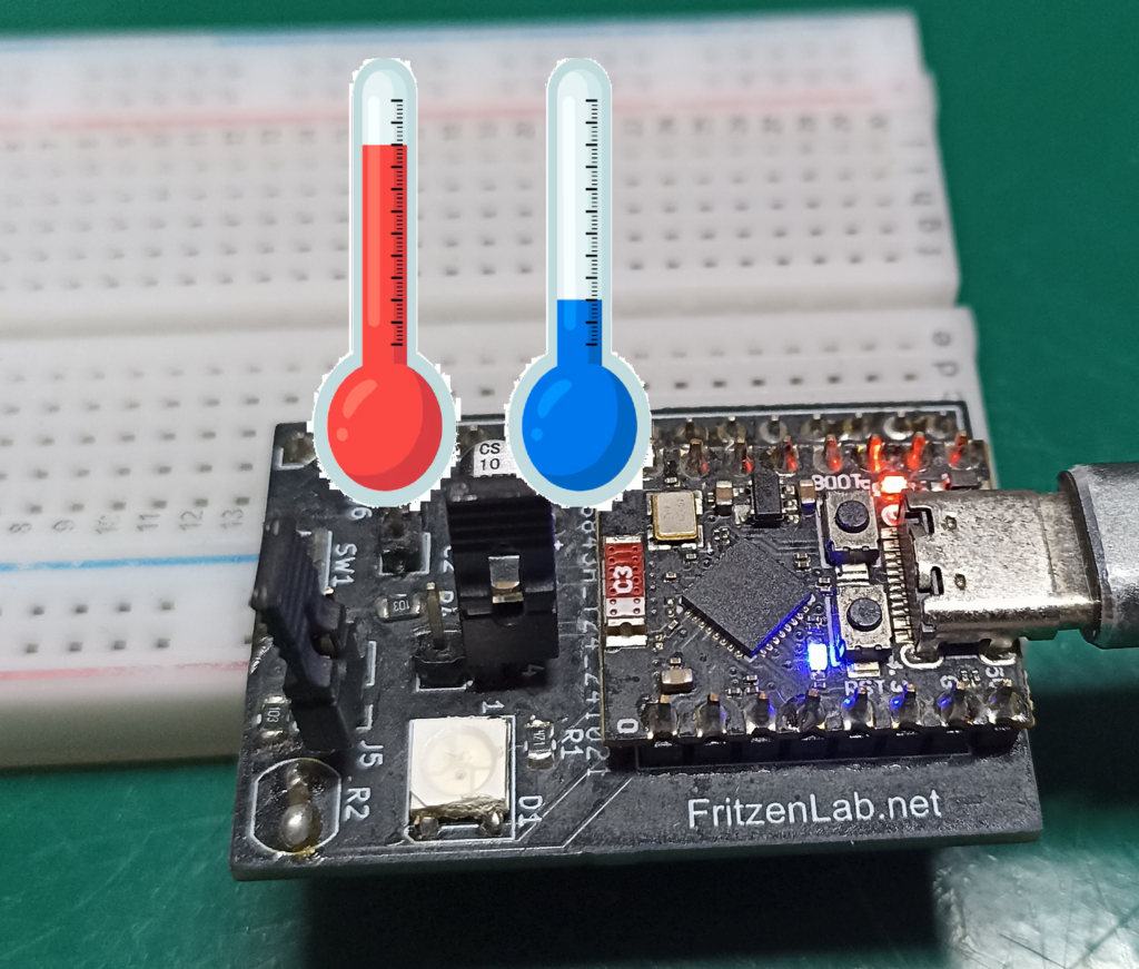
#include "driver/temperature_sensor.h"Also we will be reading an external NTC thermistor, for comparison. NTC stands for “negative temperature coefficient”, which means its value of resistance goes down with temperature going up. We have talked about NTC thermistors here and here before. They are essentially resistors whose resistance varies with temperature.
Since they are not linear, meaning their “curve” is not a “straight”, there is the need for some equations to interpret them. I have tried to implement such reading inside a PIC microcontroller before, it had not enough memory to execute it. It was a PIC12F675 with 1kB memory.
Our ESP32-C3 Super mini, in the other hand, does have enough memory for this task, so no worries. I have implemented the reading of both sensors every 500ms (0.5 seconds). It means that both the NTC and the internal temperature sensor will be read every 500ms. They will then be printed on the serial monitor/Serial plotter, as you wish.
Coding for the sensor
Open the Arduino IDE and paste the code below. Notice that only tho includes are necessary, one for the internal sensor and one for the math done for the NTC thermistor. One also has to define a couple of constants for the NTC thermistor, like the NTC’s beta, voltage VCC and series resistor value.
// Espressif official documentation on the internal sensor >> https://docs.espressif.com/projects/esp-idf/en/stable/esp32c3/api-reference/peripherals/temp_sensor.html
#include <Arduino.h>
#include "driver/temperature_sensor.h"

/* ---------- NTC CONFIG ---------- */
const int pinTermistor = 3;
const float beta = 3950.0;
const float r0   = 10000.0;
const float t0   = 273.15 + 25.0;
const float vcc  = 3.3;
const float R    = 9810.0;
const int samples = 5;

float internaltemp= 0;
int processingTime= 0;

// Internal temperature sensor function declaration
#ifdef __cplusplus
extern "C" {
#endif
uint8_t temprature_sens_read();
#ifdef __cplusplus
}
#endif

/* ---------- SETUP ---------- */
void setup() {
  Serial.begin(115200);

  analogReadResolution(12);
  analogSetAttenuation(ADC_11db);
}

/* ---------- LOOP ---------- */
void loop() {

  if(millis()  - processingTime > 500){
    processingTime= millis();
    int adcSum = 0;
    for (int i = 0; i < samples; i++) {
      adcSum += analogRead(pinTermistor);
      delay(50);
    }

    float adc = adcSum / (float)samples;
    float v   = (vcc * adc) / 4095.0;
    float rt  = (vcc * R / v) - R;

    float tempK = beta / log(rt / (r0 * exp(-beta / t0)));
    float tempC = tempK - 273.15;

    internaltemp= readInternalTemp(); // internal temperature reading

    Serial.print("NTC:");
    Serial.print(tempC);
    Serial.print(" Internal:");
    Serial.println(internaltemp);
  }

}
float readInternalTemp() {
  temperature_sensor_config_t config = TEMPERATURE_SENSOR_CONFIG_DEFAULT(10, 60);
  temperature_sensor_handle_t handle;
  ESP_ERROR_CHECK(temperature_sensor_install(&config, &handle));
  ESP_ERROR_CHECK(temperature_sensor_enable(handle));
  float temp;
  ESP_ERROR_CHECK(temperature_sensor_get_celsius(handle, &temp));
  ESP_ERROR_CHECK(temperature_sensor_disable(handle));
  ESP_ERROR_CHECK(temperature_sensor_uninstall(handle));
  return temp;
}
Variable processingTime stores the last time the main function was entered, making sure it is entered again every 500ms. Function to read the internal temperature of the ESP32-C3 was handed to me by ChatGPT, is seen below. According to it, those are a bunch of internal functions of ESP-IDF.
float readInternalTemp() {
  temperature_sensor_config_t config = TEMPERATURE_SENSOR_CONFIG_DEFAULT(10, 60);
  temperature_sensor_handle_t handle;
  ESP_ERROR_CHECK(temperature_sensor_install(&config, &handle));
  ESP_ERROR_CHECK(temperature_sensor_enable(handle));
  float temp;
  ESP_ERROR_CHECK(temperature_sensor_get_celsius(handle, &temp));
  ESP_ERROR_CHECK(temperature_sensor_disable(handle));
  ESP_ERROR_CHECK(temperature_sensor_uninstall(handle));
  return temp;
}
For the NTC thermistor, these are the equations necessary to obtain temperature from resistance. Notice the use of log() and exp() (exponential), which are the responsible for making this processor-heavy.
float adc = adcSum / (float)samples;
    float v   = (vcc * adc) / 4095.0;
    float rt  = (vcc * R / v) - R;

    float tempK = beta / log(rt / (r0 * exp(-beta / t0)));
    float tempC = tempK - 273.15;
End result and video explanation
Paste the complete code above in the Arduino IDE and click “upload” (with you ESP32-C3 connected to the computer’s USB). Code will immediately start running, all you have to do is open the Arduino IDE’s serial plotter. Go to “Tools > Serial plotter”.
You will see something like the image below, where in yellow is the NTC and in purple the internal sensor.
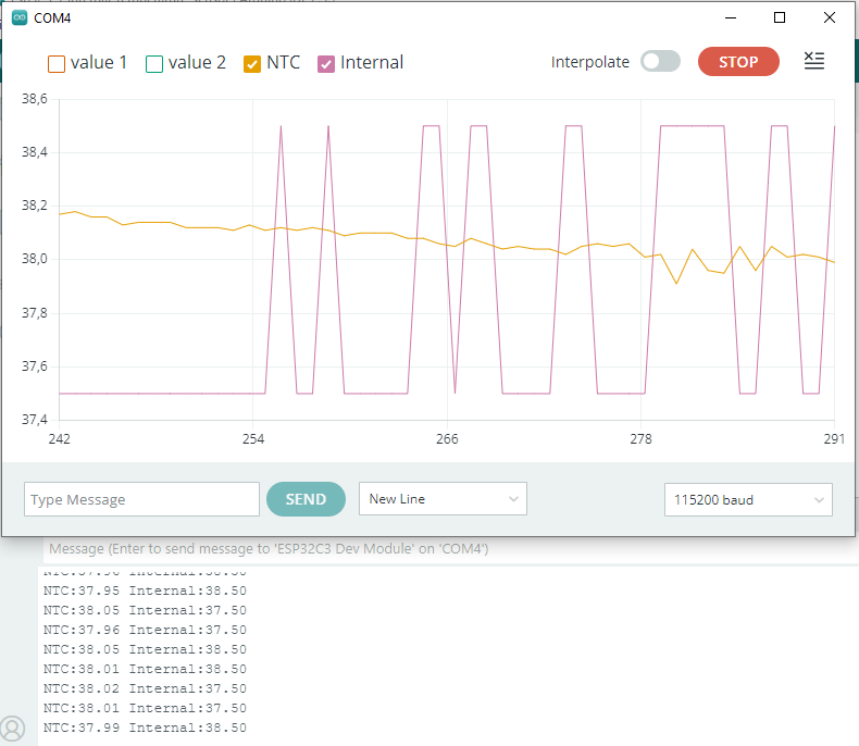
The internal temperature looks more “square”, less analog. It may be due to it having less granularity, meaning it varies in less “steps”. In the case above you can see it varies between 37.5 and 38.5 degrees Celsius. Monitor serial will output something like the text below.
NTC:37.74 Internal:37.50
NTC:37.75 Internal:38.50
NTC:37.76 Internal:38.50
NTC:37.76 Internal:37.50
Here is a video of the system working, enjoy. Here I explain you a bit of the code then show you the circuit board I made for my ESP32-C3 Super mini. Then I show you the serial monitor and serial plotter of the Arduino IDE.