The 555 integrated circuit is well known in the world of electronics. Let’s now learn how to make a timer with 555. Its datasheet lists some of the functions it can do:
- Timer
- pulse generator
- Delay generator
- PWM (pulse width modulation)
- PPM (pulse position modulation)
- Linear ramp generator
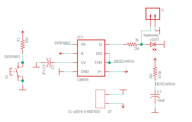
The theory of operation of the integrated circuit in this mode (timing) is as follows: When pressing button S1, capacitor C1 begins to be charged through RA. When the voltage across it reaches 66.6% of the nominal (supply) voltage, the Q output goes high.
The capacitor is then discharged through the DIS pin, so the cycle begins again. The equation for calculating the components is below.
In this article we will make a timer of a few seconds with the 555. The schematic diagram made in Eagle CAD is below. All files can be downloaded here.

Calculations
The time calculation is done as below. I used this website (digikey) to calculate the values.
T = 1.1 * RA * C1 = 1.1 * 470000 * 0.00001 = 5170ms
This means that the time counted will be a little more than 5 seconds. Then at the end of the count, an LED (LED1) will be turned on and output J1 will go high (12V). Note that if you want to use the J1 output, you will have to remove the LED1 LED.
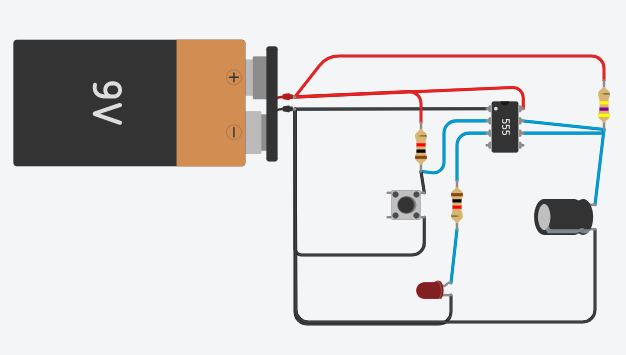
The schematic diagram is below (in TinkerCAD). The simulation is at this link.

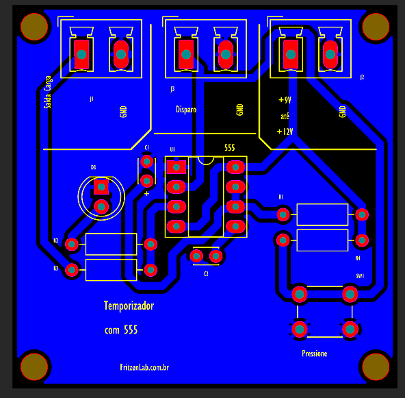
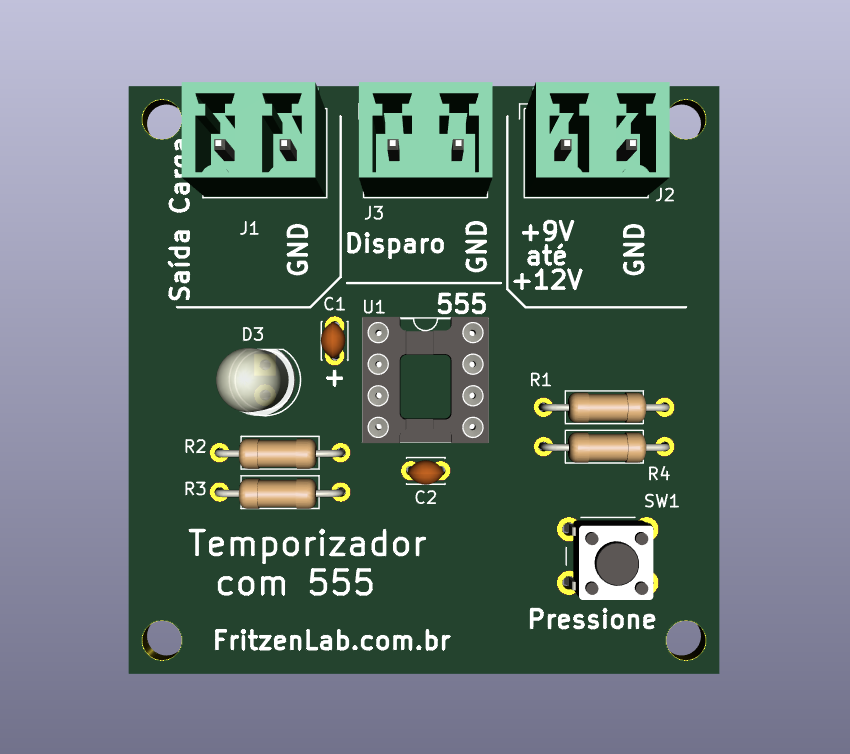
If you are interested, this link has all the printed circuit board manufacturing files, which can also be seen below.


An important tip is that you can remove the button (push-button) and use this input for your signal, coming from an external circuit. In addition to removing the LED and using the J1 output, as already mentioned.
This integrated circuit is very versatile, see also application of PWM and oscillator (blinker) with it. With that in mind, see you in the next articles.