Let us learn how to control LED brightness the fancy way, using an analog sensor as feedback. The objective is to control the brightness of an LED from 0% to 100%, without hiccups or gray zones. We are going to be implementing a feedback loop with one LED and one LDR (light dependent resistor).
But why? what is the purpose of this? This is a study on feedback loops and control electronics.
Essentially the idea is to be able to control the brightness of an LED from a potentiometer, which is an analog component. Its resistance varies with the position of its cursor, generally in a < 180º rotation fashion. The potentiometer will set the point from 0% to 100% and the LED will follow, almost as in a closed loop.
To account for environmental light variations, a recalibration happens every six minutes (360,000 miliseconds). That is automatic, the system simply knows it is time to recalibrate. It is also fast, being executed in four seconds and resuming operation right after.
The problem with LED brightness
Look at a random 5mm LED datasheet from the internet, like this one. You are always going to find a graph like the one below, forward voltage vs forward current. Note that it does not show anything below 2.8, 2.9V and 1 mA, it is simply not there. There is also not a clear indication of the starting point where current starts producing actual light.

If you ever decide to dimmerize your LED, most likely you will use PWM (pulse width modulation). The way PWM works is that what varies is the duty cycle, the time it stays in HIGH versus the time it stays in LOW. So the frequency does not vary. Want to have a primer on PWM? read this article of mine.
All of that means that if you implement a 0-100% PWM, most likely the LED brightness wil have some “gray” or unused zones. This is since a 0-100% PWM will cause the voltage to excursion between 0-3.3V or 0-5V. And that range is not fully used by the LED to actually vary brightness, that of course depends on the current circulating. This is exatctly what we saw in the graph above.
Often times (all the times, I hope) ones inserts a resistor in series with the LED, for current limiting. That resistor is calculated for a single voltage point, meaning it works to limit that exact current at that exact voltage. When you apply a PWM to an LED, that voltage varies and consequently the current.
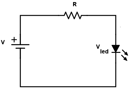
That creates a two-variable problem, current and voltage swinging together. It happens because a diode (which is what an LED is) is not linear in its behaviour. This is where a feedback with a sensor comes in handy.
We will used the full knob excursion for the full LED brightness
The solution I found
A full range PWM (0-100%) will not produce a full range brightness variation. At least not one that uses the entire PWM for the whole brightness level. What if we can calibrate the PWM, so that we know exactly at which PWM level to start and end?.
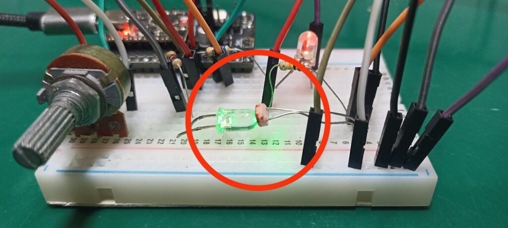
That is exactly what I am proposing in this article, using a light level sensor to read the whole LED brightness spectrum. The image below illustrates that, you can see a green LED pointed straight at an LDR face.
Myself (and ChatGPT) came up with an algorithm that does essentially two things:
- Turns the LED first ON then OFF and saves both analog values read by the LDR. These are the upper and lower limits.
- Dimmerizes the LED from 0 to 255 using analogWrite() function from Arduino. Those 255 steps represent the 8-bit PWM output of ESP32-C3, also found on the Arduino UNO boards.
That way it is possible for us to know at which voltage exactly our specific LED starts emitting light. It is also determined at which voltage it stops increasing brightness. To account for environment light variations, I execute both calibrations every six minutes.
Once the calibration happens, those limits (upper and lower) are fixed and will be used for the next six minutes. It means that our circuit is not a closed loop per se. This is since in between calibrations the current brightness is neither read nor corrected.
Electronic circuit and assembly
I am going to be using an ESP32-C3 Super mini microcontroller for this experiment. Nothing special, you can use virtually any Arduino or ESP32 model you want. Just keep in mind that you need a full range analog input and also output (actually PWM capability). That rules out ESP8266, since its analog input is only 1.1V versus its 3.3V required supply.
Our list of materials is as follow:
- ESP32-C3 Super Mini
- Breadboard 400+ points.
- 1k – 100k Ohm (any value really) Potentiometer 1 turn.
- One LDR light sensor.
- Two identical LEDs. Could be 3mm or 5mm and virtually any color.
- One 10k Ohm resistor for the LDR
- Two 680 Ohm resistors for the LEDs.
The reason we will need two identical LEDs is because both have important functions. One is the control, being read by the LDR light sensor. The other will actually be visible with the light level we apply. They need to be identical because electronics components many times are sensible to batches during fabrication.
It means that different batches will produce slightly different LEDs. This is the same that happens when building some kinds of amplifiers. Both transistors have to be almost identical in order to not create distortions and eventually destroy the circuit.
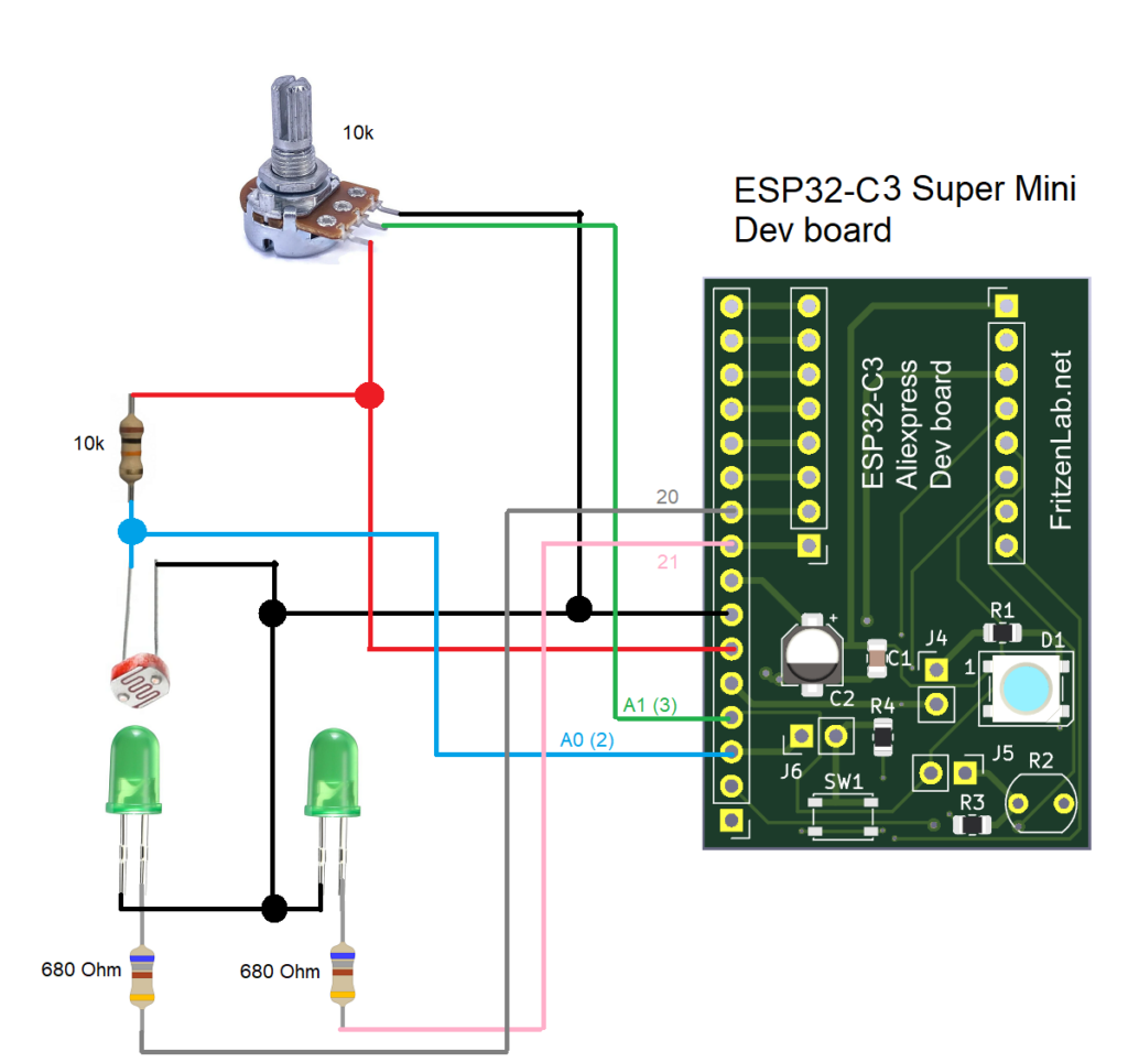
Our LDR sensor goes on pin 2 (A0), while the potentiometer goes on pin 3 (A1). The control loop LED goes on pin 20 and its twin goes on pin 21. Important to let you know that virtually any Arduino-compatible board will be good for this experiment. It is enough if it features analog inputs and PWM outputs.
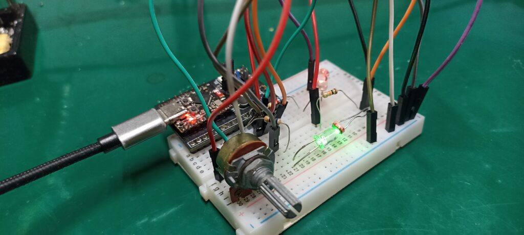
I assembled my circuit on a 400 points breadboard, a small one. It got a bit messy due to the huge jumper wires I have. But at the end of the day it works, that is what is important.
The code
As mentioned before, I came up with the idea and ChatGPT helped me with the code. Of course it made mistakes, so it took me a fair amount of time to make it all work. The ideia is to initially execute a calibration. So that we know the maximum and mininum values the LDR sensor will read for the LED ON and OFF. That ON/OFF initial calibration takes exactly two seconds.
Then we execute a ramp on the LED voltage, from 0 (0V) to 255 (3.3V). That serves to understand where on that scale (0-255) are the minimum and maximum brightness. That takes another 2.04 seconds and is executed automatically every six minutes. So both calibrations take up a total of 4.04 seconds and happen without user intervention every six minutes.
Finally we enter the doFeedback() function, where we read a potentiometer and convert that into a 0-100 integer. Such value is then used to turn the LED on accordingly, using a analogWrite() function. Such function takes up 0-255 values, so we first have to convert 0-100 to 0-255 using map().
// ---------------------------
// HARDWARE PINS
// ---------------------------
#define LDR_PIN      2
#define POT_PIN      3
#define LED_PIN      20
#define LED_SHOW     21

int ambientValue = 0;        // LDR value with LED off
int maxValue = 0;            // LDR value with LED fully on

int swipeStartPct = 0;       // when LED light first appears
int swipePeakPct  = 0;       // when LED light begins to fall again

unsigned long stateStartTime = 0;
unsigned long lastLEDChange  = 0;
unsigned long lastCalibrationCheck = 0;

bool inCalibration = true;
bool inSwipe = false;
bool blinkState = false;

int operationTime= 0;
int ledValue= 0;
int finalLedValue= 0;
int readPot= 0;
bool startProgram= false;
int counter= 0;

void setup() {
  Serial.begin(115200);

  pinMode(LED_PIN, OUTPUT);
  analogWrite(LED_PIN, 0);

  stateStartTime = millis();
  lastCalibrationCheck = millis();
}

void loop() {

  // -------------------------------------------------------
  // 1) CALIBRATION PHASE
  // This is where we find the minimum and maximum amount of light emitted
  // -------------------------------------------------------
  if (inCalibration) {
    doCalibration();
    return;  // do not continue to the rest of the loop
  }
  // -------------------------------------------------------
  // 2) SWIPE DETECTION (only once per calibration)
  // This is where the minimum and maximum brightness per voltage are found, which is
  // different from minumum and maximum voltage by themselves.
  // e.g an LED may start emitting light at for example 0.8V and stop increasing emitions at 2.2V,
  // while the datasheet says it is a 2.5V LED
  // -------------------------------------------------------
  if (inSwipe) {

    doSwipeDetection();
    return;
  }
  // -------------------------------------------------------
  // 3) OPERATION
  // -------------------------------------------------------
    doFeedback();
  // -------------------------------------------------------
  // 4) AUTO-RECALIBRATION EVERY 60 SECONDS
  // -------------------------------------------------------
  if (millis() - lastCalibrationCheck > 360000UL) {
    startCalibration();
    lastCalibrationCheck = millis();
  }
}
// =====================================================================
// CALIBRATION
// =====================================================================
void doCalibration() {

  unsigned long elapsed = millis() - stateStartTime;

  // --- Step 1: LED OFF for 1 second
  if (elapsed <= 1000) {
    analogWrite(LED_PIN, 0);
    ambientValue = 4095 - analogRead(LDR_PIN);
    return;
  }

  // --- Step 2: LED ON for another 1 second
  if (elapsed > 1000 && elapsed <= 2000) {
    analogWrite(LED_PIN, 255);     // strong LED
    int v = 4095 - analogRead(LDR_PIN);
    if (v > maxValue) maxValue = v;
    return;
  }

  // --- Calibration done
  analogWrite(LED_PIN, 0);

  Serial.println("=== Calibration Completed ===");
  Serial.print("Ambient: "); Serial.println(ambientValue);
  Serial.print("Max:     "); Serial.println(maxValue);

  // Move to swipe detection
  if(ambientValue < 100 && maxValue < 800){
    Serial.println("Still inside calibration");
  } else {
    inCalibration = false;
    inSwipe = true;
    stateStartTime = millis();  // reset for swipe
  }
}

// =====================================================================
// SWIPE DETECTION
// =====================================================================
void doSwipeDetection() {

  int lastValue = 4095 - analogRead(LDR_PIN);
  bool riseFound = false;

  Serial.println("=== Swipe Start ===");

  // Sweep LED 0→255
  for (int pwm = 0; pwm <= 255; pwm++) {

    analogWrite(LED_PIN, pwm);
    delay(8);

    int v = 4095 - analogRead(LDR_PIN);
    if(v < lastValue && riseFound == false){
      riseFound= true;
      swipePeakPct= map(lastValue, 0, 4095, 0, 100);
    }else if(v >= lastValue && riseFound == false){
      swipeStartPct= map(lastValue, 0, 4095, 0, 100);
    }else if(riseFound == true && v < lastValue){

    }
    lastValue = v;
  }

  analogWrite(LED_PIN, 0);  // end sweep

  Serial.println("=== Swipe Detection Completed ===");
  Serial.print("Start at %: "); Serial.println(swipeStartPct);
  Serial.print("Peak  at %: "); Serial.println(swipePeakPct);

  inSwipe = false;             // finished swipe
  stateStartTime = millis();   // reset timer
  startProgram= true;
}

void doFeedback(){
  if(startProgram == true){
    if(millis() - operationTime > 50){
      operationTime= millis();
      readPot= analogRead(POT_PIN);
      ledValue= map(readPot, 0, 4095, ambientValue, maxValue); // map from potentiometer to LDR calibrated values
      finalLedValue= map(ledValue, ambientValue, maxValue, 0, 255); // now map (potentiometer calibrated to LDR) to PWM
      //analogWrite(LED_PIN, finalLedValue);
      analogWrite(LED_SHOW, finalLedValue);
      counter++;
    }
    if(counter == 10){
      counter= 0;
      Serial.print("ledValue= ");
      Serial.println(ledValue);
      Serial.print("finalLedValue= ");
      Serial.println(finalLedValue);

    }
  }
}


// =====================================================================
// START A NEW CALIBRATION
// =====================================================================
void startCalibration() {
  Serial.println("\n=== Starting Recalibration ===\n");

  ambientValue = 0;
  maxValue = 0;
  swipeStartPct = 0;
  swipePeakPct = 0;

  inCalibration = true;
  inSwipe = false;

  stateStartTime = millis();
  startProgram= false;
}
End result and video demonstration
You first turn the ESP32-C3 Super Mini on, via a USB cable. Conect such USB cable to your computer, open the Arduino IDE. Then copy the code above and paste into the IDE. Then click the green arrow to the left “->” on the top left of the screen to upload the code.
After that initial upload you can supply the system with 5V directly, via the VIN pin. Or keep the USB cable connected to the computer, your choice. Wait the initial four seconds after power up, then turn the potentiometer. You will immediately see the brightness of the LED change, along with the potentiometer knob.
Notice what happens when you give the potentiometer a full turn. The LED brightness goes from 0% to 100% following the same percentual in the potentiomter knob. That is very different from a simple PWM-LED example you may find on the internet. Those examples make the LED stay OFF for long before lighting. Also the LED will reach full brightness before the potentiometer reachs 100% level.
In other words, the example you just implemented uses the full knob excursion for the full LED brightness.
I made a video explainig the experiment, along with the circuit and code. Enjoy and as always, subscribe to my Youtube Channel. See you guys in the next few articles.


Pingback: You have never seen an LED used like this - HMI - FritzenLab electronics