Today’s tutorial will teach you how to create a home automation with ESP32 and Google Home, using Sinric app and service. Our objective is to control an LED with voice commands from an Android cellphone. Sinric Pro is a service that bridges the gap between hardware (ESP32, etc) and online services like IFTTT and Google Home.
It allows up to three devices for free (of which we will use one); after that you have to pay US$3 per devicer per year. They provide Arduino libraries for Arduino IDE for the ESP32 to work. While creating this tutorial I used mostly this one from CircuitDigest as inspiration.
It contains all steps necessary for project execution, exept the voice command part (which is done in your cellphone and depends on your Android version). I used Android 13 for writing this tutorial. First thing you have to do is create an account in Sinric Pro, going to https://sinric.pro/.
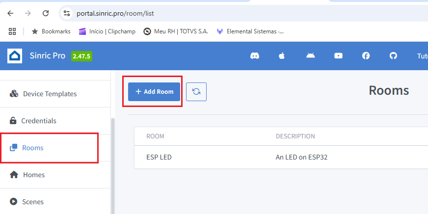
After creating your account, enter Sinric Pro website and click on “Rooms” on the left side menu. Then click “Add Room” button. Fill “Room name” and “description” with any information you like, then click “Save”.
Now we are going to add a device to a room. On the left side menu click “Devices” then “Add device”. We will create two devices: one output (LED) and one input (LM35 analog sensor). An ID will be generated for every device, save that to use later in the Arduino code.
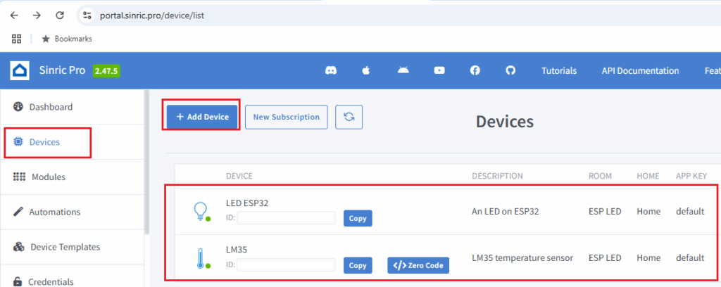
You can see my two devices in the image above. You have to provide a name, description and device type for each entry. That could be “Smart light bulb” for the LED and “Temperature sensor” for the LM35. Finally click “Save” for each device created. Finally on the left side menu, click “Credentials”.
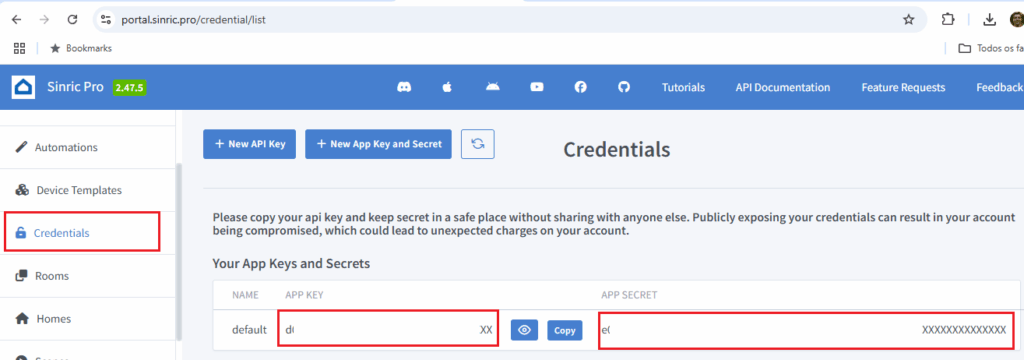
Copy and store safely both the “APP KEY” and “APP SECRET” to use in the Arduino code below. DO NOT share those credentials with anyone, nor post on the internet, they are yours only.
Hardware connections
As stated before, we will use an ESP32 for this tutorial. It could literally be any ESP32 model, since all we need is an analog input, digital IO and WiFi. We will use an LED and a push button as IOs: LED will be controlled both by Google Home and the button. A LM35 analog sensor will read environment temperature and relay it to Google Home.
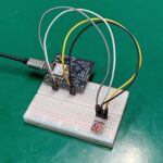
In my case I am using an ESP32-C3 Super Mini, which can be found here on my affiliate link. I made a custom circuit board to contain such ESP32-C3 board, whose information is here. Circuit will be assembled on a 400-points breadboard, more than enough for what we need.
Schematic diagram with all components represented is below. Power supply comes via USB-C cable from your computer. Notice that LM35 needs 4+ volts, so I am supplying it with 5V. IO’s in the other hand support only 3V3, so I supply the push button circuit with such voltage.
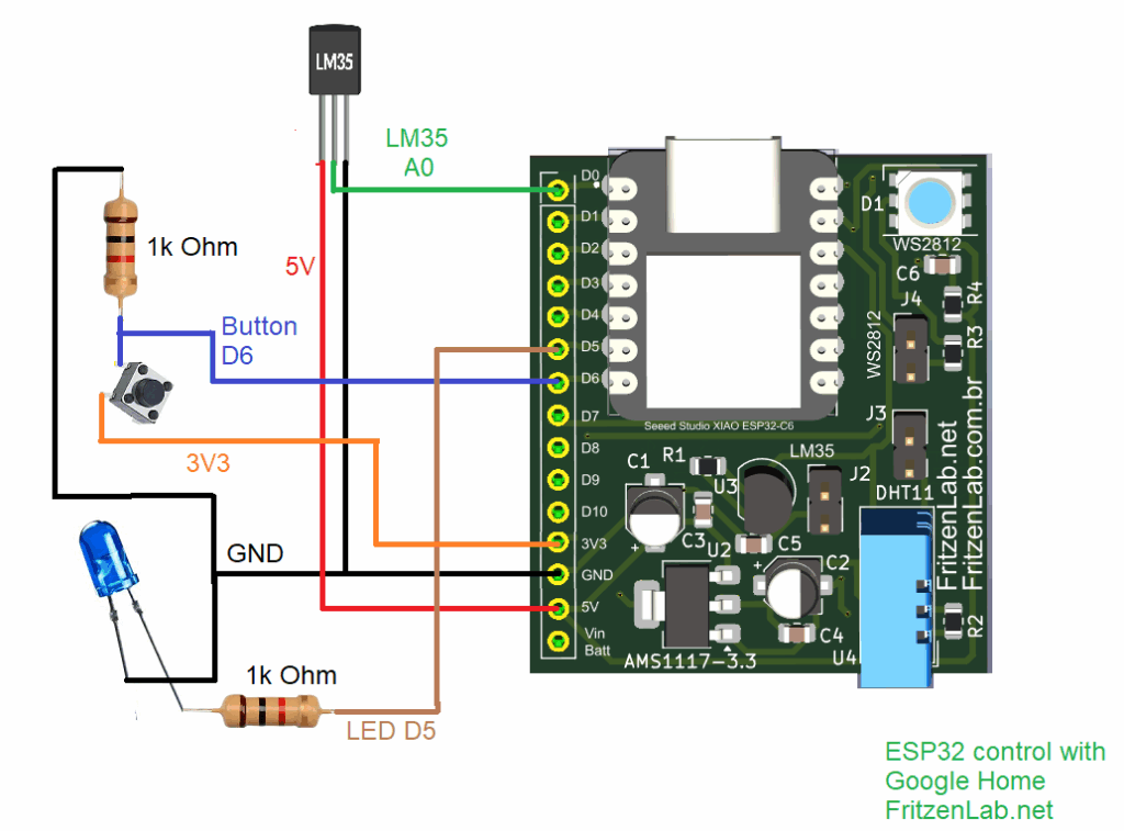
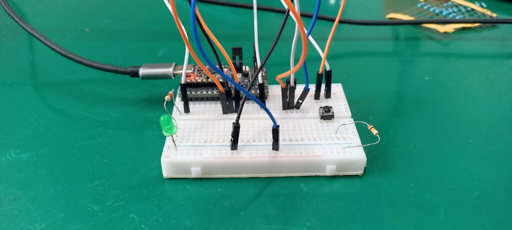
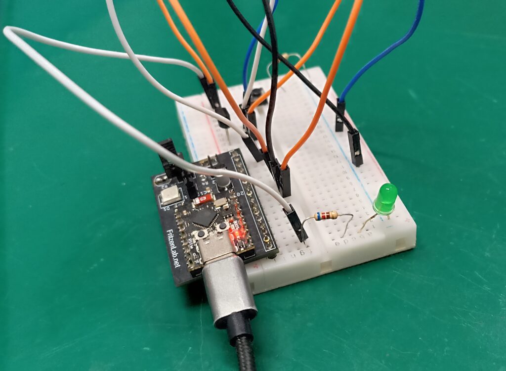
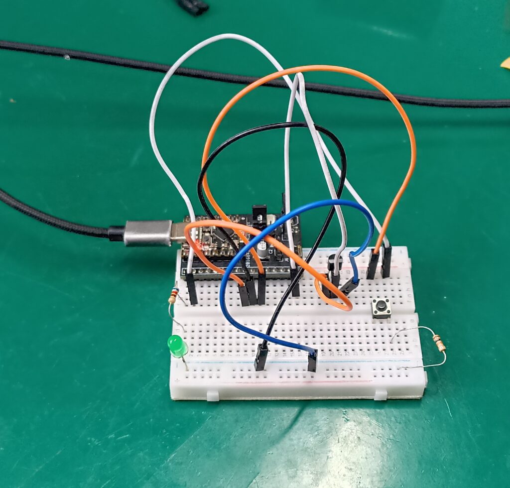
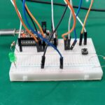
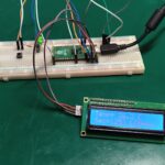
You can see pictures os the breadboard assembly below, complete with all components illustrated above.
Arduino code
As stated above, we will be programming this tutorial in Arduino code, using Arduino IDE 2.3.5-nightly. You can use any other version as long as it is above 2.2.0 (library issues). First thing you have to do is install support for your board inside the Arduino IDE. For ESP32 and ESP8266 these are the links: https://dl.espressif.com/dl/package_esp32_index.json, http://arduino.esp8266.com/stable/package_esp8266com_index.json . Put those links in “File > Preferences > Additional boards”.
Now you have to install three libraries, “Sinric Pro”, “WebSockets’ and “ArduinoJson”. To do that you go to “Sketch > Include library > Manage libraries” and type:
- “Sinric Pro” (install the one by Boris Jaeger)
- “WebSockets” (install the one by Marks Sattler)
- “ArduinoJson” (install the one by Benoit Blanchon)
Full Arduino code is below for you to use. As stated it was based on work from CircuitDigest. You can also get the same code from my GitHub repository. After the code below I will explain some important parts to you.
#include <Arduino.h>
#include <WiFi.h>
#include "SinricPro.h"
#include "SinricProSwitch.h"
#include "SinricProTemperaturesensor.h"
#define WIFI_SSID ""
#define WIFI_PASS ""
#define APP_KEY "" // Should look like "de0bxxxx-1x3x-4x3x-ax2x-5dabxxxxxxxx"
#define APP_SECRET "" // Should look like "5f36xxxx-x3x7-4x3x-xexe-e86724a9xxxx-4c4axxxx-3x3x-x5xe-x9x3-333d65xxxxxx"
#define device_ID ""
#define TEMP_SENSOR_ID "" // Should look like "5dc1564130xxxxxxxxxxxxxx" (Get it from Portal -> Devices)
#define RELAY_PIN 5
#define SWITCH_PIN 6
#define LM_PIN A0
#define wifiLed 8
#define BAUD_RATE 9600
#define DEBOUNCE_TIME 250
float temperature; // actual temperature
float humidity; // actual humidity
float lastTemperature; // last known temperature (for compare)
#define ADC_VREF_mV 3300.0 // 5000 is the voltage provided by MCU. If you connect to 3V change to 3000
#define ADC_RESOLUTION 4096.0
#define EVENT_WAIT_TIME 20000
bool lastSwitchState = false;
unsigned long lastSwitchChange = 0;
bool relayState = false;
bool onSwitchPowerState(const String& deviceId, bool &state) {
relayState = state;
digitalWrite(RELAY_PIN, relayState);
return true;
}
bool onSensorPowerState(const String &deviceId, bool &state) {
return true; // request handled properly
}
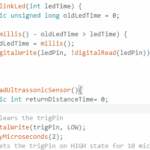
float getTemperature() {
#if defined(ESP8266)
int analogValue = analogRead(LM_PIN);
float millivolts = (analogValue / 1024.0) * ADC_VREF_mV;
float temperature = millivolts / 10;
// float fahrenheit = ((temperature * 9) / 5 + 32);
return temperature;
#elif defined(ESP32)
int adcVal = analogRead(LM_PIN);
float milliVolt = adcVal * (ADC_VREF_mV / ADC_RESOLUTION);
float temperature = milliVolt / 10;
return temperature;
#endif
}
void handleTemperaturesensor() {
if (SinricPro.isConnected() == false) {
Serial.printf("Not connected to Sinric Pro...!\r\n");
return;
}
static unsigned long last_millis;
unsigned long current_millis = millis();
if (last_millis && current_millis - last_millis < EVENT_WAIT_TIME) return;
last_millis = current_millis;
float temperature = getTemperature();
Serial.printf("Temperature: %2.1f °C\r\n", temperature);
if (isnan(temperature)) { // reading failed...
Serial.printf("reading failed!\r\n"); // print error message
return; // try again next time
}
if (temperature == lastTemperature) {
Serial.printf("Temperature did not changed. do nothing...!\r\n");
return;
}
SinricProTemperaturesensor &mySensor = SinricPro[TEMP_SENSOR_ID]; // get temperaturesensor device
bool success = mySensor.sendTemperatureEvent(temperature, -1); // send event
if (success) {
Serial.printf("Sent!\r\n");
} else {
Serial.printf("Something went wrong...could not send Event to server!\r\n"); // Enable ENABLE_DEBUG to see why
}
lastTemperature = temperature; // save actual temperature for next compare
}
void handleSwitch() {
unsigned long currentMillis = millis();
bool switchState = digitalRead(SWITCH_PIN);
if (switchState != lastSwitchState) {
if (currentMillis - lastSwitchChange > DEBOUNCE_TIME) {
if (switchState) {
relayState = !relayState; // Toggle the relay state
digitalWrite(RELAY_PIN, relayState);
SinricProSwitch &mySwitch = SinricPro[device_ID];
mySwitch.sendPowerStateEvent(relayState);
}
lastSwitchChange = currentMillis;
}
lastSwitchState = switchState;
}
}
void setupWiFi()
{
Serial.printf("\r\n[Wifi]: Connecting");
WiFi.begin(WIFI_SSID, WIFI_PASS);
while (WiFi.status() != WL_CONNECTED)
{
Serial.printf(".");
delay(250);
}
digitalWrite(wifiLed, HIGH);
Serial.printf("connected!\r\n[WiFi]: IP-Address is %s\r\n", WiFi.localIP().toString().c_str());
}
void setupSinricPro() {
SinricProSwitch& mySwitch = SinricPro[device_ID];
mySwitch.onPowerState(onSwitchPowerState);
SinricProTemperaturesensor &mySensor = SinricPro[TEMP_SENSOR_ID];
//mySensor.onPowerState(onSensorPowerState);
SinricPro.begin(APP_KEY, APP_SECRET);
SinricPro.restoreDeviceStates(false);
}
void setupRelay() {
pinMode(RELAY_PIN, OUTPUT);
//digitalWrite(RELAY_PIN,HIGH); // Initialize relay in the OFF state
}
void setupSwitch() {
pinMode(SWITCH_PIN, INPUT);
}
void setup() {
Serial.begin(BAUD_RATE);
pinMode(wifiLed, OUTPUT);
digitalWrite(wifiLed, LOW);
setupRelay();
setupSwitch();
setupWiFi();
setupSinricPro();
}
void loop() {
SinricPro.handle();
handleSwitch();
handleTemperaturesensor();
}
A couple of important things:
- The way this code works, temperature in degrees Celsius is sent to the cloud (Sinric and Google Home). Push button will turn the LED on and OFF. Google Home will also turn the same LED ON and OFF, via Sinric Pro.
- “WIF_SSID” and “WIFI_PASS” will be filled with by you with your Wi-Fi credentials.
- “APP_KEY” and “APP_SECRET” are available to you (and you only) on your Sinric Pro account.
- “device_ID” is a unique string to the instance created inside Sinric Pro. This is your LED. Same goes to “TEMP_SENSOR_ID”, which is your LM35.
- “ADC_Vref_mv” is the voltage with which your LM35 is supplied.
- “ADC_resolution” is an integer representing the analog-to-digital channel resoltion. In our case it is 4096 integers because our ESP32 AD converter is 12 bit.
- “EVENT_WAIT_TIME” is the time interval (in milliseconds) between analog readings from LM35.
You can edit what is necessary (list above) then upload the code to your ESP32. At this point you will already be able to control and read your board from the Sinric platform, going to https://portal.sinric.pro/dashboard .
Google Home app configuration
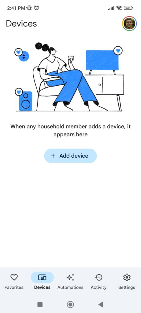
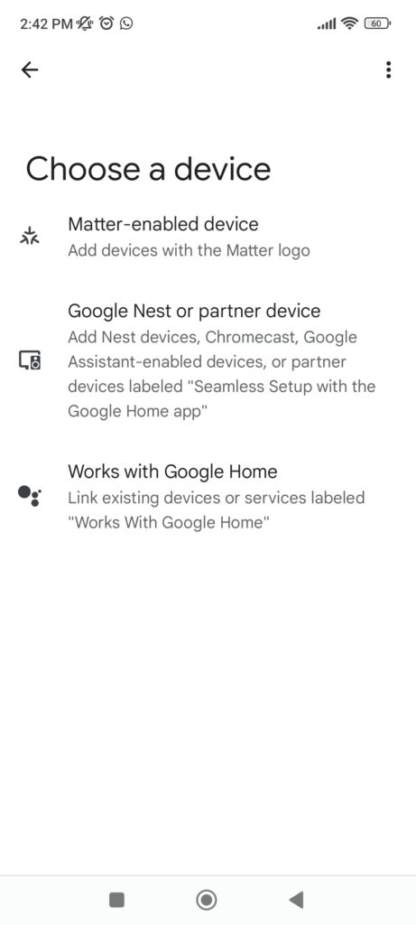
Now get your Android cellphone and download “Google Home” from the Play store. Opening the App, there is going to be a “+ Add device” button, click it. Now you have to pick “Works with Google Home” option, click on it.
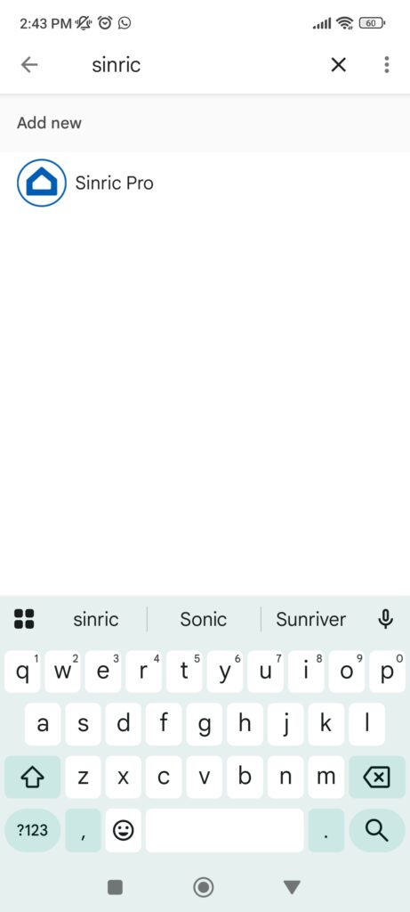
Now click the magnifier glass (search button) and type “Sinric”. Click the Sinric Pro icon.
You have to link your Sinric accout to Google, click “Continue” and log in (e-mail and password for your Sinric Pro account). Click “Sign in”.
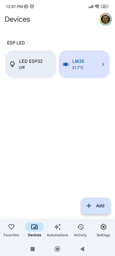
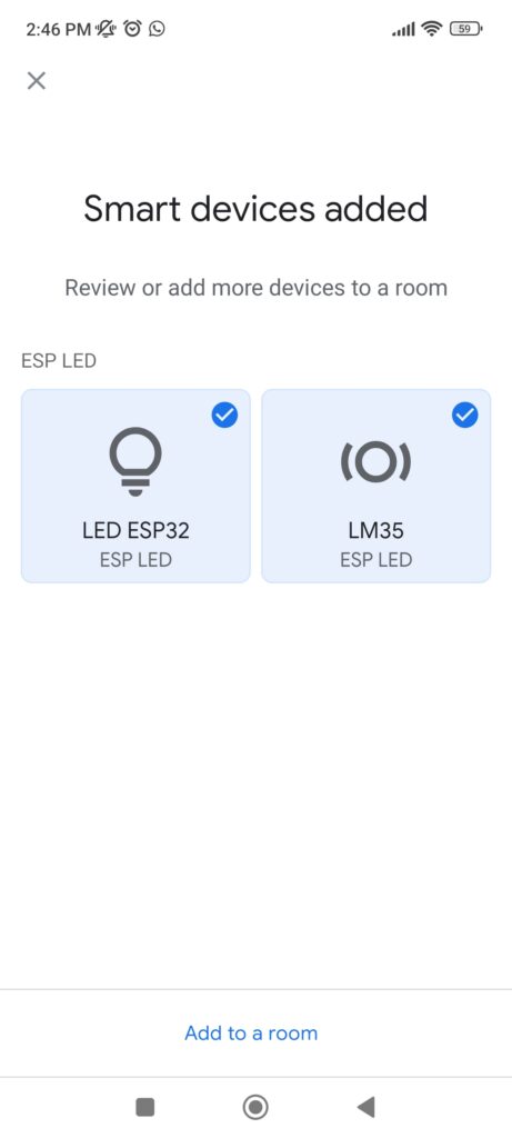
Both our devices (LED and LM35) will show on screen, click the “tick” sign on top of each, both will turn blue. Then click “Add to a Room”.
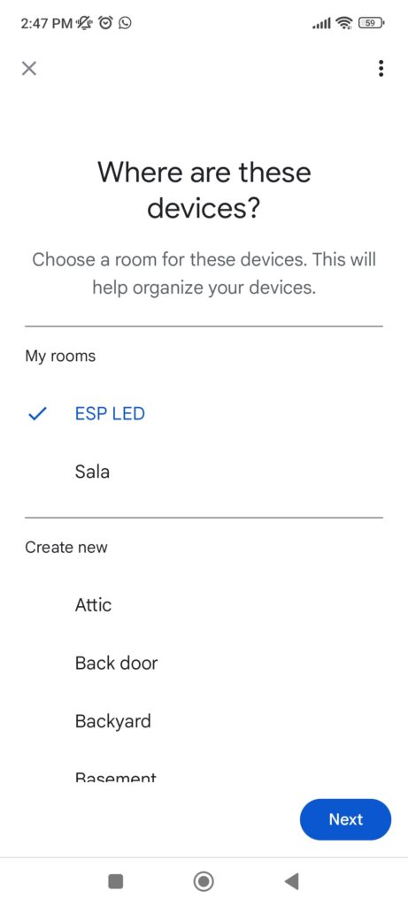
You can pick any room you want. I have created one called “ESP LED”. Click on it and then “Next”.
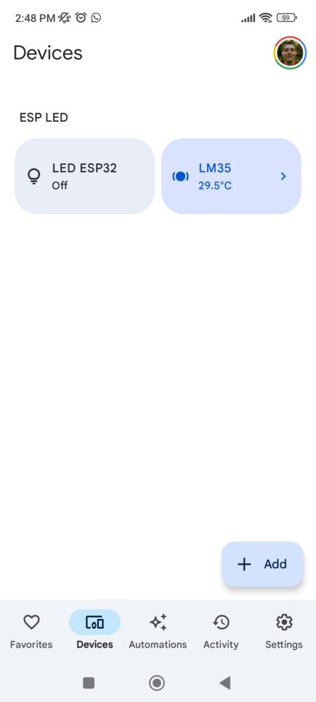
You will be back to the previous screen, just click the “x” on the top left, then the “<-” left arrow on the top left. You are finally back to the “Devices” screen, where both your devices are now available.
Usage and testing
You can now click the button you just created inside Google Home, and see the LED of ESP32 turning ON and OFF. In my experience it takes a couple of seconds (and sometimes clicks) for the APP to stabilize and behave. Temperature readings do not update by themselves, you have to click the LM35 button to see it changing.
You can control the LED via voice commands, by adding an “Automation” from within the Google Home app itself. Click “Automations” on the bottom of the app, then the “+” (plus, Create) sign. Now pick between “HouseHold” or “Personal”; I am choosing personal since I am the only one tinkering with the device.
In “how this routine will start” click “+ Add Starter” then select “When I say to Google Assistant”. Get and type a distinct phrase, like “Turn LED on” and click “Add starter”. In “Actions” click “+ Add action” and click “Adjust Home Devices”. Click on your LED (just created) then click “Turn on or off”; select “Turn on” and click “Add Action”.
Click “Save” at the bottom of the screen. Repeat the two paragraphs above but now with the phrase “Turn LED off” and selecting “Turn off” as action. Now activate the Google assistant (or Google Gemini) in your cellphone. In my Android version I press the power button for half a second.
It will be listening, so you just say “Turn LED on” or “Turn LED off” and look what happens to the LED on ESP32. I made a very complete video showing everything you need to know about this project (at the top of the post). Enjoy and post your question down there in the comments. If you want to buy the ESP32-C3 Super mini used in this experiment, click my affiliate link.


Leave a Reply