This article will teach you how to use a LCD display made easy with micropython, with the Raspberry Pi Pico 2 board. We will be using the Thonny IDE software for programming. There is going to be a button, one LED and one temperature sensor (LM35).
The system will work as follow:
- A 16×2 LCD display will display information about time, button state and temperature,
- A button will turn an LED ON and OFF,
- An LM35 analog temperature sensor will sensor the environment.
- There will be no sleep() or delay() in the code, it will all be non-blocking.
All of that will be assembled on a 800-points breadboard. My intentions with this article and experiment are to show you that one can implement a bunch of functions in a single code and project. Our Pi Pico 2 will handle different pheripherals, all while not blocking any code execution. Micropython will be the language of choice this time, since I have been tinkering with it a lot lately.
Functional description
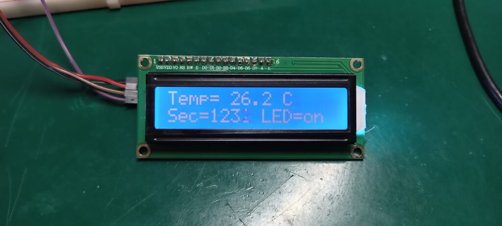
Look at the image below, the final version of the display software. It features three things: environment temperature, seconds counter and LED state.
First thing I will talk about is the LCD display itself. It is a 16×2 (16 columns and 2 lines) model, communicating to my Pi Pico 2 via i2c. A library is needed for that, so I found this one on RandomNerdTutorials. File structure is two support files (the “library”) and the “main.py” code.
First file is the “lcd_api.py”, seen below. In thonny IDE, with you Raspberry Pi Pico 2 already connected (via USB), you should open a new file and copy/paste the code below. Then save it INSIDE THE PI as “lcd_api.py”.
# Provides an API for talking to HD44780 compatible character LCDs.
# https://github.com/dhylands/python_lcd/tree/master/lcd
import time

class LcdApi:
    """Implements the API for talking with HD44780 compatible character LCDs.
    This class only knows what commands to send to the LCD, and not how to get
    them to the LCD.

    It is expected that a derived class will implement the hal_xxx functions.
    """

    # The following constant names were lifted from the avrlib lcd.h
    # header file, however, I changed the definitions from bit numbers
    # to bit masks.
    #
    # HD44780 LCD controller command set

    LCD_CLR = 0x01              # DB0: clear display
    LCD_HOME = 0x02             # DB1: return to home position

    LCD_ENTRY_MODE = 0x04       # DB2: set entry mode
    LCD_ENTRY_INC = 0x02        # --DB1: increment
    LCD_ENTRY_SHIFT = 0x01      # --DB0: shift

    LCD_ON_CTRL = 0x08          # DB3: turn lcd/cursor on
    LCD_ON_DISPLAY = 0x04       # --DB2: turn display on
    LCD_ON_CURSOR = 0x02        # --DB1: turn cursor on
    LCD_ON_BLINK = 0x01         # --DB0: blinking cursor

    LCD_MOVE = 0x10             # DB4: move cursor/display
    LCD_MOVE_DISP = 0x08        # --DB3: move display (0-> move cursor)
    LCD_MOVE_RIGHT = 0x04       # --DB2: move right (0-> left)

    LCD_FUNCTION = 0x20         # DB5: function set
    LCD_FUNCTION_8BIT = 0x10    # --DB4: set 8BIT mode (0->4BIT mode)
    LCD_FUNCTION_2LINES = 0x08  # --DB3: two lines (0->one line)
    LCD_FUNCTION_10DOTS = 0x04  # --DB2: 5x10 font (0->5x7 font)
    LCD_FUNCTION_RESET = 0x30   # See "Initializing by Instruction" section

    LCD_CGRAM = 0x40            # DB6: set CG RAM address
    LCD_DDRAM = 0x80            # DB7: set DD RAM address

    LCD_RS_CMD = 0
    LCD_RS_DATA = 1

    LCD_RW_WRITE = 0
    LCD_RW_READ = 1

    def __init__(self, num_lines, num_columns):
        self.num_lines = num_lines
        if self.num_lines > 4:
            self.num_lines = 4
        self.num_columns = num_columns
        if self.num_columns > 40:
            self.num_columns = 40
        self.cursor_x = 0
        self.cursor_y = 0
        self.implied_newline = False
        self.backlight = True
        self.display_off()
        #self.backlight_on()
        self.clear()
        self.hal_write_command(self.LCD_ENTRY_MODE | self.LCD_ENTRY_INC)
        self.hide_cursor()
        self.display_on()

    def clear(self):
        """Clears the LCD display and moves the cursor to the top left
        corner.
        """
        self.hal_write_command(self.LCD_CLR)
        self.hal_write_command(self.LCD_HOME)
        self.cursor_x = 0
        self.cursor_y = 0

    def show_cursor(self):
        """Causes the cursor to be made visible."""
        self.hal_write_command(self.LCD_ON_CTRL | self.LCD_ON_DISPLAY |
                               self.LCD_ON_CURSOR)

    def hide_cursor(self):
        """Causes the cursor to be hidden."""
        self.hal_write_command(self.LCD_ON_CTRL | self.LCD_ON_DISPLAY)

    def blink_cursor_on(self):
        """Turns on the cursor, and makes it blink."""
        self.hal_write_command(self.LCD_ON_CTRL | self.LCD_ON_DISPLAY |
                               self.LCD_ON_CURSOR | self.LCD_ON_BLINK)

    def blink_cursor_off(self):
        """Turns on the cursor, and makes it no blink (i.e. be solid)."""
        self.hal_write_command(self.LCD_ON_CTRL | self.LCD_ON_DISPLAY |
                               self.LCD_ON_CURSOR)

    def display_on(self):
        """Turns on (i.e. unblanks) the LCD."""
        self.hal_write_command(self.LCD_ON_CTRL | self.LCD_ON_DISPLAY)

    def display_off(self):
        """Turns off (i.e. blanks) the LCD."""
        self.hal_write_command(self.LCD_ON_CTRL)

    def backlight_on(self):
        """Turns the backlight on.

        This isn't really an LCD command, but some modules have backlight
        controls, so this allows the hal to pass through the command.
        """
        self.backlight = True
        self.hal_backlight_on()

    def backlight_off(self):
        """Turns the backlight off.

        This isn't really an LCD command, but some modules have backlight
        controls, so this allows the hal to pass through the command.
        """
        self.backlight = False
        self.hal_backlight_off()

    def move_to(self, cursor_x, cursor_y):
        """Moves the cursor position to the indicated position. The cursor
        position is zero based (i.e. cursor_x == 0 indicates first column).
        """
        self.cursor_x = cursor_x
        self.cursor_y = cursor_y
        addr = cursor_x & 0x3f
        if cursor_y & 1:
            addr += 0x40    # Lines 1 & 3 add 0x40
        if cursor_y & 2:    # Lines 2 & 3 add number of columns
            addr += self.num_columns
        self.hal_write_command(self.LCD_DDRAM | addr)

    def putchar(self, char):
        """Writes the indicated character to the LCD at the current cursor
        position, and advances the cursor by one position.
        """
        if char == '\n':
            if self.implied_newline:
                # self.implied_newline means we advanced due to a wraparound,
                # so if we get a newline right after that we ignore it.
                self.implied_newline = False
            else:
                self.cursor_x = self.num_columns
        else:
            self.hal_write_data(ord(char))
            self.cursor_x += 1
        if self.cursor_x >= self.num_columns:
            self.cursor_x = 0
            self.cursor_y += 1
            self.implied_newline = (char != '\n')
        if self.cursor_y >= self.num_lines:
            self.cursor_y = 0
        self.move_to(self.cursor_x, self.cursor_y)

    def putstr(self, string):
        """Write the indicated string to the LCD at the current cursor
        position and advances the cursor position appropriately.
        """
        for char in string:
            self.putchar(char)

    def custom_char(self, location, charmap):
        """Write a character to one of the 8 CGRAM locations, available
        as chr(0) through chr(7).
        """
        location &= 0x7
        self.hal_write_command(self.LCD_CGRAM | (location << 3))
        self.hal_sleep_us(40)
        for i in range(8):
            self.hal_write_data(charmap[i])
            self.hal_sleep_us(40)
        self.move_to(self.cursor_x, self.cursor_y)

    def hal_backlight_on(self):
        """Allows the hal layer to turn the backlight on.

        If desired, a derived HAL class will implement this function.
        """
        pass

    def hal_backlight_off(self):
        """Allows the hal layer to turn the backlight off.

        If desired, a derived HAL class will implement this function.
        """
        pass

    def hal_write_command(self, cmd):
        """Write a command to the LCD.

        It is expected that a derived HAL class will implement this
        function.
        """
        raise NotImplementedError

    def hal_write_data(self, data):
        """Write data to the LCD.

        It is expected that a derived HAL class will implement this
        function.
        """
        raise NotImplementedError

    # This is a default implementation of hal_sleep_us which is suitable
    # for most micropython implementations. For platforms which don't
    # support `time.sleep_us()` they should provide their own implementation
    # of hal_sleep_us in their hal layer and it will be used instead.
    def hal_sleep_us(self, usecs):
        """Sleep for some time (given in microseconds)."""
        time.sleep_us(usecs)  # NOTE this is not part of Standard Python library, specific hal layers will need to override this
Second file is called “machine_i2c_lcd.py”, containing (amongst other things) the display i2c address (which you should change to contemplate your part at hand). On Thonny IDE also open a blank new file and copy/paste the code below, saving it TO THE PI, no the computer.
# Implements a HD44780 character LCD connected via PCF8574 on I2C.
# This was tested with: https://www.wemos.cc/product/d1-mini.html
# https://github.com/dhylands/python_lcd/blob/master/lcd/machine_i2c_lcd.py

from lcd_api import LcdApi
from time import sleep_ms

# The PCF8574 has a jumper selectable address: 0x20 - 0x27
DEFAULT_I2C_ADDR = 0x3D

# Defines shifts or masks for the various LCD line attached to the PCF8574

MASK_RS = 0x01
MASK_RW = 0x02
MASK_E = 0x04
SHIFT_BACKLIGHT = 3
SHIFT_DATA = 4


class I2cLcd(LcdApi):
    """Implements a HD44780 character LCD connected via PCF8574 on I2C."""

    def __init__(self, i2c, i2c_addr, num_lines, num_columns):
        self.i2c = i2c
        self.i2c_addr = i2c_addr
        self.i2c.writeto(self.i2c_addr, bytearray([0]))
        sleep_ms(20)   # Allow LCD time to powerup
        # Send reset 3 times
        self.hal_write_init_nibble(self.LCD_FUNCTION_RESET)
        sleep_ms(5)    # need to delay at least 4.1 msec
        self.hal_write_init_nibble(self.LCD_FUNCTION_RESET)
        sleep_ms(1)
        self.hal_write_init_nibble(self.LCD_FUNCTION_RESET)
        sleep_ms(1)
        # Put LCD into 4 bit mode
        self.hal_write_init_nibble(self.LCD_FUNCTION)
        sleep_ms(1)
        LcdApi.__init__(self, num_lines, num_columns)
        cmd = self.LCD_FUNCTION
        if num_lines > 1:
            cmd |= self.LCD_FUNCTION_2LINES
        self.hal_write_command(cmd)

    def hal_write_init_nibble(self, nibble):
        """Writes an initialization nibble to the LCD.

        This particular function is only used during initialization.
        """
        byte = ((nibble >> 4) & 0x0f) << SHIFT_DATA
        self.i2c.writeto(self.i2c_addr, bytearray([byte | MASK_E]))
        self.i2c.writeto(self.i2c_addr, bytearray([byte]))

    def hal_backlight_on(self):
        """Allows the hal layer to turn the backlight on."""
        self.i2c.writeto(self.i2c_addr, bytearray([1 << SHIFT_BACKLIGHT]))

    def hal_backlight_off(self):
        """Allows the hal layer to turn the backlight off."""
        self.i2c.writeto(self.i2c_addr, bytearray([0]))

    def hal_write_command(self, cmd):
        """Writes a command to the LCD.

        Data is latched on the falling edge of E.
        """
        byte = ((self.backlight << SHIFT_BACKLIGHT) | (((cmd >> 4) & 0x0f) << SHIFT_DATA))
        self.i2c.writeto(self.i2c_addr, bytearray([byte | MASK_E]))
        self.i2c.writeto(self.i2c_addr, bytearray([byte]))
        byte = ((self.backlight << SHIFT_BACKLIGHT) | ((cmd & 0x0f) << SHIFT_DATA))
        self.i2c.writeto(self.i2c_addr, bytearray([byte | MASK_E]))
        self.i2c.writeto(self.i2c_addr, bytearray([byte]))
        if cmd <= 3:
            # The home and clear commands require a worst case delay of 4.1 msec
            sleep_ms(5)

    def hal_write_data(self, data):
        """Write data to the LCD."""
        byte = (MASK_RS | (self.backlight << SHIFT_BACKLIGHT) | (((data >> 4) & 0x0f) << SHIFT_DATA))
        self.i2c.writeto(self.i2c_addr, bytearray([byte | MASK_E]))
        self.i2c.writeto(self.i2c_addr, bytearray([byte]))
        byte = (MASK_RS | (self.backlight << SHIFT_BACKLIGHT) | ((data & 0x0f) << SHIFT_DATA))
        self.i2c.writeto(self.i2c_addr, bytearray([byte | MASK_E]))
        self.i2c.writeto(self.i2c_addr, bytearray([byte]))
Second component I want to show you about is the LM35 temperature sensor. We have talked about it here already, have a look. Its datasheet (here) says it works from -55ºC to +150ºC, with an output grade of 10mV/ºC. This means that (for example) for 20ºC it would output 200mV. It needs 4V or more of power supply, so we will be supplying it with the +5V from the Pi Pico 2 board.
Since its output for room temperature is around 200mV, we don’t need to worry about range. Our Pi Pico 2 reads up to 3V3 in its analog inputs, but we are far away from that with the LM35. We are also showing a seconds counter on the second line of the display, starting from zero at startup and going up indefinitely. As stated before, we are not using sleep on this code. Instead I do the structure below using “time.ticks_ms().
if time.ticks_diff(time.ticks_ms(), initialtime) > 100: # this IF will be true every 1000 ms
            initialtime= time.ticks_ms() #update with the "current" time
That essentially only enters the IF statement every time 100ms. That’s the minimum amount of time that the code does anything, nothing is faster than 100ms in my code. I then create a varible called “counter”, that is updated every 1000ms. It is shown on the LCD as follow:
lcd.putstr(str(counter))“Counter” is a varible that holds integers, so I have to convert it to String in order to show on the 16×2 LCD display. Then finally I show the state of one LED on screen, “on” or “off”, by doing this:
if (ledon):
                    lcd.putstr("on")
                else:
                    lcd.putstr("off")
Such LED is turn ON and OFF by the press of a push button. I also do software debounce for the button, “delaying” readings for 400ms after every reading.
Hardware/connections
Today’s hardware connections are a bit more extensive than I normally do here on the blog. We have i2c for the LCD display, analog for the LM35 sensor, digital input for push button and digital output for LED. Everything is drawn below for you to look and copy. Notice I do not use any kind of filter, capacitor, inductor, etc. For bench experiments, specially involving no high frequency, you can skip that.
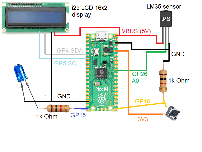
Regarding the resistors pictured in the schematic, I put both at 1k Ohm. The one for the LED should be that or lower, while the one for the push button should be that or higher (10k Ohm for example). Acting as a pull down to guarantee logic level low, the resistor for the push button is not critical.
A note on the i2c port I used (pins 4 and 5): those are the i2c0 “main” standard i2c pins, but you can pick (and program) other pins if you like. The same choice applies for the analog input for the LM35, you can pick a port from A0 to A2.
Firmware/code
As already stated, we will be programming this example using the Thonny IDE software, capable of working with Raspberry Pi Pico 2 over USB. Also as stated before, my code does not use any blocking “delay()” or “sleep()” function. It means you could add other functions without worrying about it not working properly.
I have given you above the two “.py” files necessary for the LCD display to work, “machine_i2c_lcd” and “lcd_api”. Other necessary functions/libraries are already built-in the Thonny IDE: Time, Pin, ADC and I2C. These are standard with microPython distributions. Full code is seen below, you should copy/paste it into a new file in Thonny IDE. Then save it ON THE PI as “main.py”.
from machine import Pin, SoftI2C, I2C, ADC
from machine_i2c_lcd import I2cLcd
import time
from time import sleep

led = machine.Pin(15, machine.Pin.OUT)
button= machine.Pin(16, machine.Pin.IN)

LM35 = ADC(Pin(26)) #ADC0
initialtime = 0
LM35C= 0
counter= 0
display= 0

buttontime= time.ticks_ms()
counting= 0
ledon= False
laststate= 1
buttonon= False
clicks= 0

# Define the LCD I2C address and dimensions
I2C_ADDR = 0x3D
I2C_NUM_ROWS = 2
I2C_NUM_COLS = 16

i2c = I2C(id=0, scl=5, sda=4, freq=400_000)
devices = i2c.scan()
print("I2C devices:", [hex(d) for d in devices])

lcd = I2cLcd(i2c, I2C_ADDR, I2C_NUM_ROWS, I2C_NUM_COLS)

try:
    while True:
        currenttime= time.ticks_ms() #Every time it passes here, gets the current time
        if time.ticks_diff(time.ticks_ms(), initialtime) > 100: # this IF will be true every 100 ms
            initialtime= time.ticks_ms() #update with the "current" time
            display= display + 1
            if(display > 9): #display is updated every 10x 100ms
                display= 0
                counter= counter + 1
                # Clear the LCD
                lcd.clear()
                # Display two different messages on different lines
                # By default, it will start at (0,0) if the display is empty
                lcd.putstr("Temp= ");
                lcd.move_to(6, 0)
                lcd.putstr(str(LM35C)+ " C")
                # Starting at the second line (0, 1)
                lcd.move_to(0, 1)
                lcd.putstr("Sec= ")
                lcd.move_to(4, 1)
                lcd.putstr(str(counter))

                lcd.move_to(9, 1)
                lcd.putstr("LED=")
                lcd.move_to(13, 1)
                if (ledon):
                    lcd.putstr("on")
                else:
                    lcd.putstr("off")


                LM35raw = LM35.read_u16() # read value, 0-65535 across voltage range 0.0v - 3.3v
                # line below converts from 16bit to volts, then rounds it to 3 places then
                # multiplies by 100 to convert from milivolts to degrees Celsius
                LM35C= round((LM35raw * 3.3 / 65535),3)*100
                print(LM35C, end= "")
                print(" C")


            if time.ticks_diff(time.ticks_ms(), buttontime) > 20: # this IF will be True every 20 ms
                buttontime= time.ticks_ms()

                if button.value() == 1 and laststate == 0:
                    clicks+= 1
                    print("LED state changed")
                    print("clicks: " + str(clicks))
                    laststate= 1
                    ledon = not ledon
                    buttonon= True
                    led.value(ledon)


                if buttonon == True and counting < 20:
                    counting+= 1

                else:
                    counting= 0
                    buttonon= False
                    laststate= 0


except KeyboardInterrupt:
    # Turn off the display
    print("Keyboard interrupt")
    lcd.backlight_off()
    lcd.display_off()
Our LCD display is controlled by the “lcd.xxx” functions, as for example “lcd.clear()” to clean the screen and “lcd.putstr()” to write a string to it.
Testing and final thoughts
After copying/pasting the complete code above to your Thonny IDE, save it to the Pi. Then you can finally run the code and see it working. Do just that by clicking the green arrow on the top of the screen (“Run current script (F5)”). What you are supposed to see is in the image and video below.
The word “Temp” is followed by the current environmental temperature around your board. Then the word “Sec” is followed by the number of integer seconds since powering the board up. Finally the word “LED” is followed by the current state of the LED, “on” or “off”.
Enjoy the video and comment below if you have any questions. Also if you want to buy the Raspberry Pi Pico 2 you can use my affiliate link here. Also get a 16×2 LCD display from here.


