Today’s post is all about creating analog voltages with Arduino code, using the SeeedStudio Xiao SAMD21 microcontroller. Said microcontroller has a single DAC module (digital to analog output), which we will use for comparison. When we talk about Arduino UNO (for example), it has no DAC module, meaning it can’t directly create analog voltages.
But for the cases where you need analog voltages (as for example a 0-10V output, let’s say), there is a simple way. Despite not being so elegant or precise, it is still a way of creating analog voltages with simple and cheap components. All you need is one capacitor and one resistor, to form a low-pass filter. You then apply PWM (pulse width modulation) to this circuit and voilá, obtain DC voltages.
Talking a bit about the board we will be using, it is based on the ATSAMD21 chip from Microchip. It is the same used in Arduino Zero and other official boards. I bought a Xiao SAMD21 from SeeeStudio, whose information you can get here. If you want to buy it, just use my affiliate links here and here.
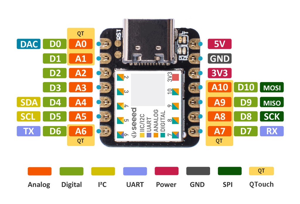
Image above brings us its pinout, you can see by the side of pins A0/D0 there is a “DAC” text in blue. That indicates the presence of a digital to analog converter, capable of outputting analog voltages. That is specially useful for (for example) audio applications and industrial automation. We will be using that DAC module/pin to compare our generared voltage against, rather as a ballast.
Filtering the PWM
As stated above, the way this “home made DAC” works is by applying a PWM signal to a RC low pass filter. We have talked about PWM before here on the blog, but it is essentially a fixed frequency signal. What varies is the period the signal stays in ON or OFF state. In Arduino case this frequency is most likely 732Hz, being possible for the tON and tOFF to vary between 0 and 100%.
The way one uses PWM in Arduino is by calling the analogWrite() function, passing an integer between 0-255 (8 bit) in Arduino UNO. For our Arduino Xiao SAMD21 we will pass a 10 bit integer (0-1023). For the filter calculations I have used this website (Digikey), where yoy enter two of three parameters: capacitor, resistor or cutoff frequency.
I entered the capacitante (1uF) and cutoff frequency 732Hz, giving me a resistor value of 217 Ohm. The closest value one I had at home was 200 Ohm, so I proceeded with it.
Schematic diagram
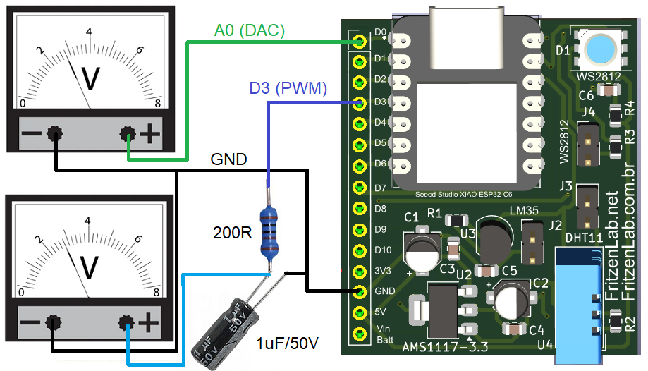
As it is usual and current here on the blog, schematic diagrams for our experiments are simple and easy to follow. For today’s experiment you need a potentiometer of any value (not depicted below), one 200R resistor and one 1uF capacitor. I recommed you get a SAMD21-based microcontroller, since we will need an on-chip DAC module.
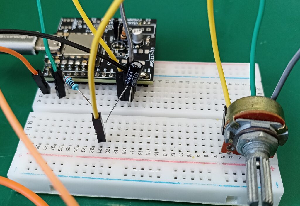
You will also need two voltmeters, one for the true/real DAC output and one for our filtered PWM one. I have my two Hikari multimeters (a Brazilian brand), HM-2010 and HM-2080. Below there is also pictures of the setup on a breadboard.

Code and simulation+experiment
Basically in this experiment we are dealing with PWM, so analogWrite() is our function of choice. I made Arduino code so that every 500ms (0.5 seconds) I read the potentiometer value and apply it directly to the DAC module and PWM. If you were to use an Arduino UNO for this experiment, you would have to be extra careful. This is since the PWM module takes 0-255 and the potentiometer would read 0-1023. You would have to use a map() function in between them.
You can see the full code below, where I use pin A0 and DAC output, A2 as potentiometer reading and pin 3 as PWM output.
#define analogOutputDAC A0
#define analogOutputPWM 3
#define analogInputPin A2

long analogTime;
bool goingUp= true;
int integerDAC= 0;
int rawAnalog= 0;

void setup() {
  // put your setup code here, to run once:
  analogWriteResolution(10);
  analogReadResolution(10);
}

void loop() {
  // put your main code here, to run repeatedly:

  if(millis() - analogTime > 500){
    analogTime= millis();

    rawAnalog= analogRead(analogInputPin);

    analogWrite(analogOutputDAC, rawAnalog);
    analogWrite(analogOutputPWM, rawAnalog); // RC low pass 1uF 200R
  }

}
Our objective today is to show a varyig analog voltage in our multimeter, from a PWM+filter circuit. To confirm that I first did a simulation in TinkerCAD, which is at this link for you to play with.
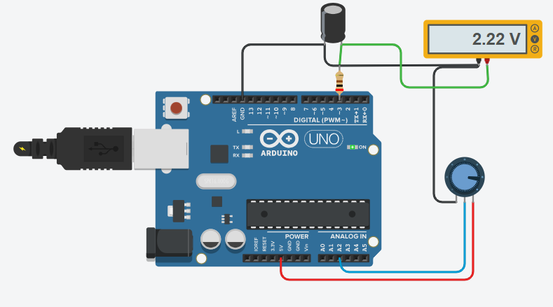
By turning the potentiometer between 0 and 100%, you can see the output voltage in the multimeter go from 0.0V to 3.3V. This confirms that the circuit and code works.
Final thoughts
We can finally to the the bench, upload the code to our Xiao SAMD21 and test the circuit with two multimeters. I made a video for you to see how this system works, enjoy!. And remeber that if you want to buy the Xiao SAMD21, use this and this links.


