Today’s post is all about the AS7341 RGB and IR light sensor, a sensor capable of showing us RGB light levels. It is also capable of showing raw light level and infrared (IR) information. This is an i2c sensor capable of communicating with any Arduino-compatible microcontroller.
For today’s post I will be using the Xiao ESP32-C3 from SeeedStudio, seen in the image below. I have made a custom circuit board for it featuring all its pins on a single row, breadboard-able. You can have more information about this board here, in its official page.
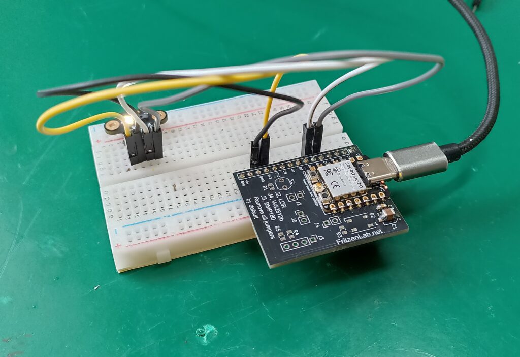
The circuit board I made supports any of the Xiao line’s microcontrollers, which are pin-compatible. It features slots for LDR light sensor, WS2812b RGB LED and BMP085 temperature and humidity sensor (none of these are populated in the image above). Talking a bit about this article’s sensor, AS7341, it is a light sensor whose capability goes being detecting light levels (as you would expect a LDR to do).
Its datasheet here states that it can measure eight “parts” of the visible spectrum of light, giving us a 16-bit (0-65535) value for each. Here is a table with all colors detected by the AS7341 IR light sensor, with spectrum-to-color provided by chatGPT:
| Channel | Wavelength (nm) | Approx. Color Name | Description |
|---|---|---|---|
| ADC0 / F1 | 415 | Violet | Deep violet, near-UV |
| ADC1 / F2 | 445 | Blue | Deep blue, similar to royal blue |
| ADC2 / F3 | 480 | Cyan / Blue-Green | Between sky blue and cyan |
| ADC3 / F4 | 515 | Green | Emerald green / spring green |
| ADC0 / F5 | 555 | Yellow-Green | Bright lime, peak eye sensitivity |
| ADC1 / F6 | 590 | Amber / Orange | Amber LED / traffic light orange |
| ADC2 / F7 | 630 | Red | Bright red |
| ADC3 / F8 | 680 | Deep Red | Dark red, nearing infrared |
This sensor can also bring us light level (just plain white light) and infrared (IR) in 16-bit fashion. Additionally there is a function to detect flickering of 50-60Hz light. You can always buy this sensor from my affiliate link on Aliexpress, here. The example I will bring to you today uses the Arduino language and comprises: reading all 8 color channels, reading white light channel, reading infrared channel and turning the onboard LED on.
Talking about the onboard LED, it is a warm-white 2700k one. According to the chip’s datasheet, it is capable of supplying up to 258mA to an external LED, controlled by a 7-bit internal register (e.g 0000000 is 4ma and 1111111 is 258mA). It is used to illuminate the subject matter for easier color detection.
Hardware
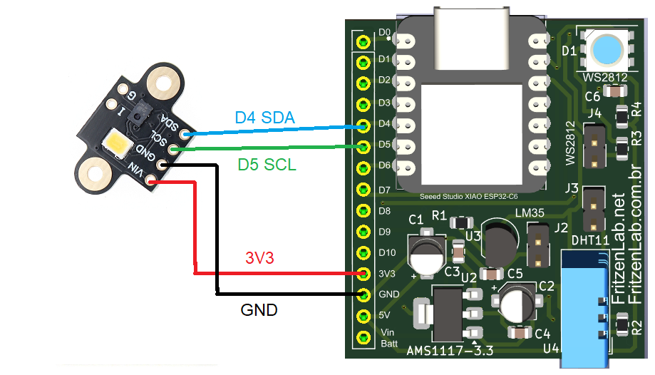
As is it usual and normal here on the board, hardware and connections are super straightforward for this experiment. AS7341’s connections are limited to i2c (SDA and SCL), 3V3 and GND. I am supplying my Xiao ESP32-C3 board with 5V from USB-C, connected to my laptop computer. One could implement and many things (peripherals) as they like, just adding things to the ESP32-C3’s available pins.
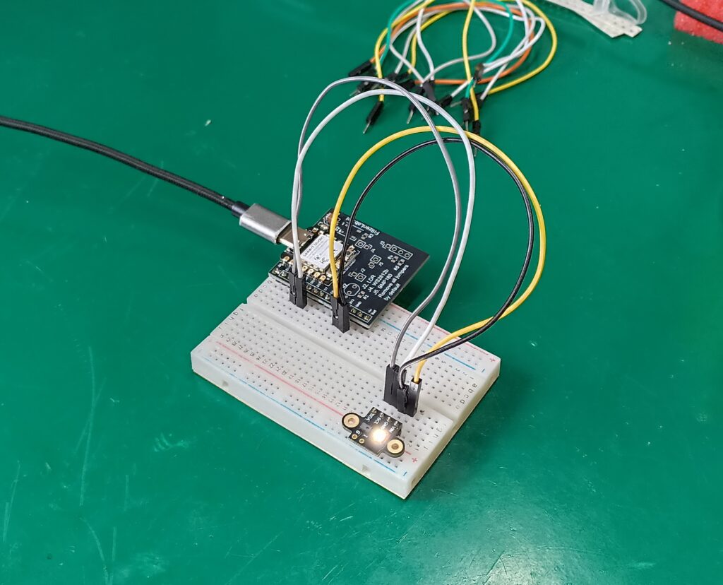
Schematic diagram is seen below, along with a picture of the assembly on a breadboard. There is no need for any pull-up or pull-down resistor, not even series one. Both the AS7341 and Xiao ESP32-C3 board take care of it.
Firmware/Arduino code
AS7341 communicates via i2c, which means it has a bunch of registers that can be read and written to. That implies the need for a library for Arduino (ESP32) to be able to communicate with it. Adafruit has a neat library for this case, available directly from within the Arduino IDE.
To install it, open the Arduino IDE (I am using version 2.3.5 nightly) and go to “Sketch > Include library > Manage libraries” and type “AS7341”. Select the one from Adafruit and click install. I have implemented a test code which is a mix of three of the available examples in “File > Examples > Adafruit AS7341”. These are “led_test”, “read_all_channels” and “flicker_detection”.
It will show you an integer for each of the eight available colors and and integer for the white light detection. Also an integer for infrared detected light, besides detecting flickering (this time a string is shown) and turning the onboard LED on.
Complete code is below and also on my Github, here.
#include <Adafruit_AS7341.h>
Adafruit_AS7341 as7341;


void setup() {
  Serial.begin(115200);

  // Wait for communication with the host computer serial monitor
  while (!Serial) {
    delay(1);
  }

  if (!as7341.begin()){
    Serial.println("Could not find AS7341");
    while (1) { delay(10); }
  }

  as7341.setATIME(100);
  as7341.setASTEP(499);
  as7341.setGain(AS7341_GAIN_256X);

  as7341.setLEDCurrent(4); // 4mA
  as7341.enableLED(true);
  delay(100);
}

void loop() {
  uint16_t readings[12];
  uint16_t flicker_freq = 0;

  flicker_freq = as7341.detectFlickerHz();

  if (!as7341.readAllChannels(readings)){
    Serial.println("Error reading all channels!");
    return;
  }

  Serial.print("ADC0/F1 415nm : ");
  Serial.println(readings[0]);
  Serial.print("ADC1/F2 445nm : ");
  Serial.println(readings[1]);
  Serial.print("ADC2/F3 480nm : ");
  Serial.println(readings[2]);
  Serial.print("ADC3/F4 515nm : ");
  Serial.println(readings[3]);
  Serial.print("ADC0/F5 555nm : ");

  /*
  // we skip the first set of duplicate clear/NIR readings
  Serial.print("ADC4/Clear-");
  Serial.println(readings[4]);
  Serial.print("ADC5/NIR-");
  Serial.println(readings[5]);
  */

  Serial.println(readings[6]);
  Serial.print("ADC1/F6 590nm : ");
  Serial.println(readings[7]);
  Serial.print("ADC2/F7 630nm : ");
  Serial.println(readings[8]);
  Serial.print("ADC3/F8 680nm : ");
  Serial.println(readings[9]);
  Serial.print("ADC4/Clear    : ");
  Serial.println(readings[10]);
  Serial.print("ADC5/NIR      : ");
  Serial.println(readings[11]);

  if (flicker_freq == 0) {
      Serial.println("No flicker detected");
  }else if (flicker_freq == 1) {
      Serial.println("Flicker detected with unknown frequency");
  }else {
      Serial.print("Flicker detected at ");
      Serial.print(flicker_freq);
      Serial.println(" Hz");
  }

  Serial.println();
}
Upon copying the code above and pasting it into your Arduino IDE, connect your Arduino or ESP32 to the computer via USB cable. Then click “upload” and wait for it to finish; finally open the serial monitor by doing “Tools > Serial monitor” or CTRL+ Shift+ M.
Results and final thoughts
By doing the above procedure you will start seeing data being printed to the serial monitor. In my experience the loop occurs every 700-800ms, which is due to the code processing time. This is since I have put no delay() function in it, I saw no need whatsoever.
Made a video with the sensor testing below for you to enjoy, where I explain a bit of the hardware, the code and the working of the whole band. Enjoy!. If you want to buy this AS7341 sensor, use my Aliexpress affiliate link here. Also have a look in another sensor I have tested in the past.


