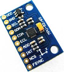
Today’s post will talk about what is supposedly a MPU-9255 Accelerometer and gyroscope. It is the first time I ask full help from Chat-GPT while coding for a project. I say it is supposedly a MPU-9255 because I got a bit of mixed results while trying to make it work.
First thing I did was to Google for “MPU-9250 accelerometer and gyroscope”, which is what I actually bought from Aliexpress (from this link). I found this Github library for microPython. I wanted to use microPython to sharpen my skills in the language. Also because I wanted to use the RP2040 Zero from Waveshare in the process (also from Aliexpress, link here). I will be programming this sensor in microPython.
I kept getting errors, at which point I actually asked Chat-GPT for help. We talked a bit back and forth until I tested this sketch (using Thonny IDE). It scans the i2c bus after valid addresses and was supposed to show me:
0x68: MPU92500x0C: AK8963 magnetometer
If 0x0C is missing, the magnetometer isn’t accessible.
from machine import I2C, Pin
i2c = I2C(0, scl=Pin(5), sda=Pin(4))  # or appropriate pins
print("I2C scan:", i2c.scan())
That’s exactly what happened, 0x0C was missing. I then Chat-GPT asked me to upload the sketch below and figure whether I was handling a MPU-9255 instead:
who_am_i = i2c.readfrom_mem(0x68, 0x75, 1)
print("WHO_AM_I:", hex(who_am_i[0]))
In fact I got 0x70 as an answer, as forecasted by the below list:
0x71-> MPU9250
0x68-> MPU6050
0x70-> MPU9255
0x19-> MPU6886
At that point I know I had a MPU-9255 and not a MPU-9250 in my hands, and even without the magnetometer. What a mess from Aliexpress parts, providing fake incomplete chips. But at least I have an accelerometer and gyroscope, let’s look at the bright side.
Hardware
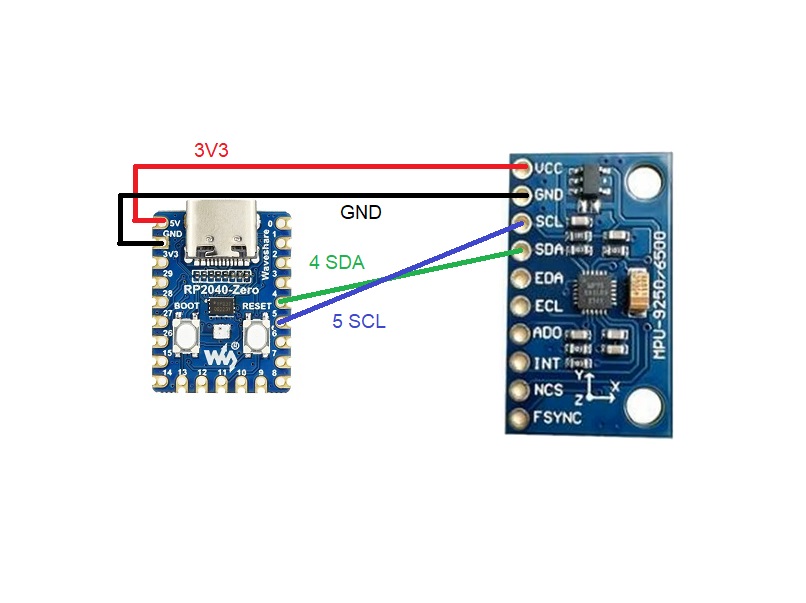
Such chip communicates to any microcontroller via i2c, which is a two-wire bus and protocol. Its datasheet is here for you to have a look. That means our breadboard assembly will be clean and quick, as usual here on the blog. All you need for this example is 3V3, GND, SDA and SCL pins. Full schematic is below, have a look.
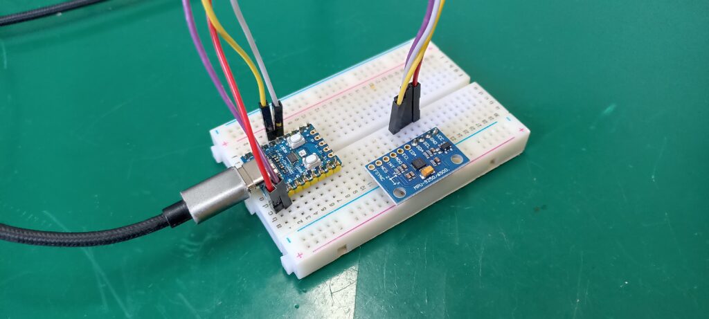
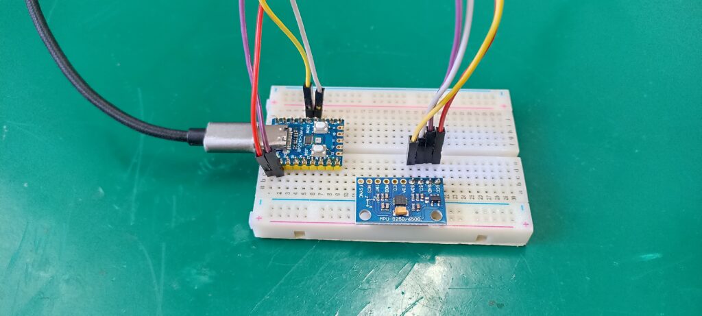
Important to note that the board I bought is supplied with 5V, not 3V3. I was having a lot of trouble trying to make it communicate via i2c. Up to the point that I looked at the PCB and saw what looked like an LDO regulator. Then I supplied it with 5V and things started working. You can see below my assembly on the breadboard.
Next you have to connect the USB-C cable between RP2040 Zero and your computer. I am using Windows and the Thonny IDE software for microPython programming.
Code/Firmware
In Thonny IDE you will connect you board (RP2040 Zero) via USB, open a new file (blank) and copy/paste the code below. Such code was entirely generated by Chat-GPT, I tested it and it seems to work.
One thing you have to be careful and thoughtful about is the i2c pinout. I connected SDA and SCL on pins 4 and 5 (respectively) of the board, which means they are on i2c “0”. RP2040 Zero can handle i2c pins in multiple locations, both for “i2c0” and “i2c1”, so it is important to populate below exactly where your pins are. See how I did, look at the schematic diagram above.
i2c = I2C(0, scl=Pin(5), sda=Pin(4)) # RP2040 examplefrom machine import I2C, Pin
import time
import struct
# I2C setup — adjust pins for your board
i2c = I2C(0, scl=Pin(5), sda=Pin(4)) # RP2040 example
MPU_ADDR = 0x68
def write_reg(reg, val):
i2c.writeto_mem(MPU_ADDR, reg, bytes([val]))
def read_bytes(reg, length):
return i2c.readfrom_mem(MPU_ADDR, reg, length)
# Initialize MPU9255 (accel/gyro only)
def mpu_init():
write_reg(0x6B, 0x00) # PWR_MGMT_1: wake up
time.sleep_ms(10)
write_reg(0x1B, 0x00) # GYRO_CONFIG: ±250°/s
write_reg(0x1C, 0x00) # ACCEL_CONFIG: ±2g
print("MPU9255 initialized (gyro/accel only)")
def read_accel():
data = read_bytes(0x3B, 6)
ax, ay, az = struct.unpack(">hhh", data)
return ax / 16384, ay / 16384, az / 16384 # Scale for ±2g
def read_gyro():
data = read_bytes(0x43, 6)
gx, gy, gz = struct.unpack(">hhh", data)
return gx / 131, gy / 131, gz / 131 # Scale for ±250°/s
# --- Main program ---
mpu_init()
while True:
ax, ay, az = read_accel()
gx, gy, gz = read_gyro()
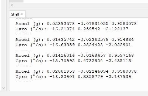
print("Accel (g):", ax, ay, az)
print("Gyro (°/s):", gx, gy, gz)
print("------")
time.sleep(0.5)Save the file INTO YOUR BOARD (not on your computer) as “main.py”. Then click the green arrow at the top of the screen “Run current script (F5)”.
End result
What you will see in Thonny IDE shell readings is below. Essentially accelerometer reading (3 axis) in G (gravity units) and gyroscopical readings in degrees per second (in all three axis).
I made a video explaining how this sensor works, for you to have an idea what it does and at which precision degree.
If you have any questions please comment below or got to Linkedin and search for “FritzenLab” page. If you want to buy material for this experiment, use my Aliexpress affiliante links. MPU-9255 here and RP2040 Zero here.


