Let’s learn how to dominate force sensitive resistor (FSR) with ESP32, using Arduino code and the Arduino IDE. A force sensitive resistor is a semiconductor “resistor” whose resistance varies with pressure applied. This amazing Adafruit guide talks a bit more about it.
Basically what happens is that there are metal “fingers” that will connect semiconductor parts. This happens more with more pressure applied, lowering the “resistor’s” total resistance. I found at least three different datasheets for the same RFP602 model I have, here, here and here.
I have the 5kg model, but one can’t expect to measure precise weights with this sensor. It is intended to be a cheap “pressure/no pressure” kind of sensor. You are going to see what I am talking about, in a while. That said, I will implement just a LED ON/LED OFF circuit and code with you.
Hardware/circuit
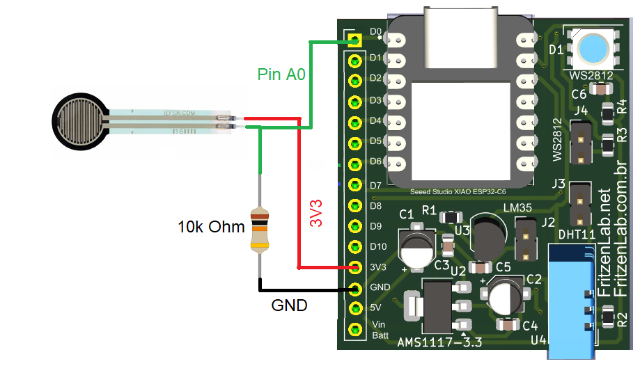
All you need to test and use and dominate force sensitive resistor is a 10k (10000) ohm resistor and a microcontroller with an analog input. Resistor will act as a resistive divider. There are various tables and graphs around the internet correlating force and resistance. I will just look at the analog values in Arduino IDE. Look at my circuit below.
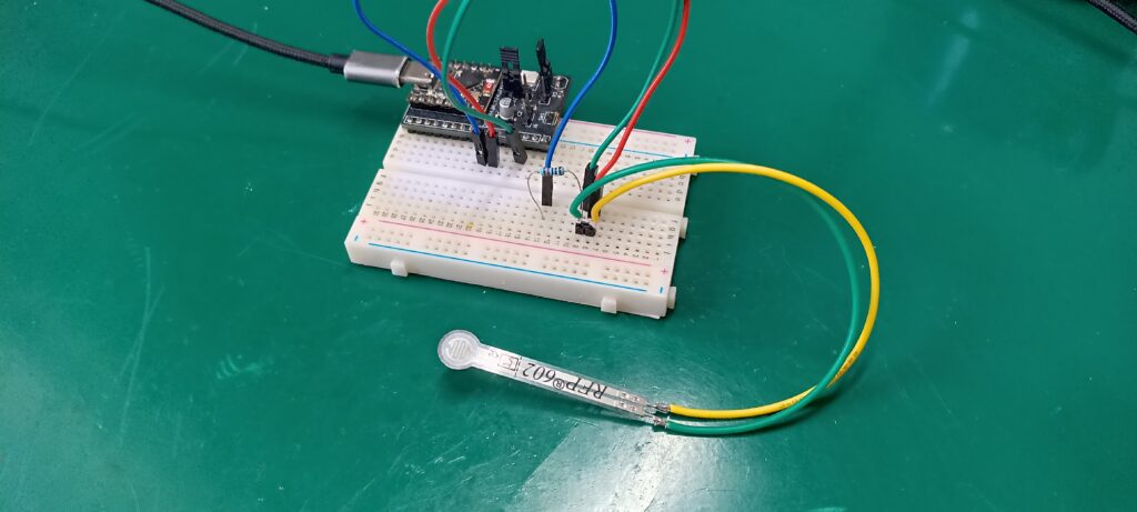
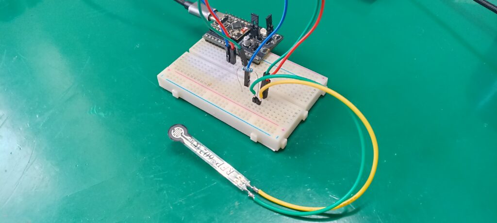
You can see I assembled the circuit in a small 400-points breadboard. This is since I made a special circuit board to fit my ESP32-C3 Super mini in such tight spaces. More details about that board here.
Firmware/code
Since we are talking about a “resistor” divider circuit, all one needs is an analog input from any microcontroller. I choose the ESP32-C3 Super mini because they feature 12 bit analog inputs. It means they can measure values between 0 and 4095 integers, 0 to 3.3V.
What my code does is basically read the analog input and send raw (0-4095) data into the Arduino IDE’s serial monitor. I then make a single IF statement to turn on the ESP32-C3’s onboard LED or not. That’s all you need to test such FSR sensor. Code is below and also in my Github.
// These constants won't change. They're used to give names to the pins used:
const int analogInPin = 2;
int sensorValue = 0;
const int led = 8;

void setup() {

  Serial.begin(115200);
  pinMode(8, OUTPUT);
}

void loop() {
  // read the analog in value:
  sensorValue = analogRead(analogInPin);


  // print the results to the Serial Monitor:
  Serial.print("sensor = ");
  Serial.println(sensorValue);

  if(sensorValue > 2400){
    digitalWrite(led, LOW); // here should be HIGH, but logic in this ESP32-C3 Super mini is inverted
  }else{
    digitalWrite(led, HIGH);
  }

  delay(250);
}
Note that I am comparing the LED ON condition to 2400, which is a value in the range 0-4095 from the analog input. This is a value that I do not understand. That’s since all around the internet it is said this FSR sensor has an “infinite” resistance when untouched. Mine is giving me values around half way 4095, and that’s what I am living with. So 2400 is an empirical value that works for me, but maybe not for you.
I recomend you use my example code above, observe what is coming in the serial monitor when the sensor is untouched and pressed. Then decide what value is best for you.
Testing and results
I uploaded the code above to my ESP32-C3 Super mini and opened the Arduino IDE’s serial monitor. Then started pressing and releasing the FSR sensor, observing the values change in the serial monitor. See the video below. If you want to buy such sensor from my affiliate Aliexpress link, click here.


Pingback: Youtube subscribers counter with ESP32 - FritzenLab electronics