Today’s post will teach you how to learn and use 433MHz radio with Arduino code and ESP32. Such radios are very low power and useful for low bit rate applications. One such application is to open/close automated gates, as well as other small home automations. In the Arduino world such radios could be used to create telemetry beacons, relaying data from sensors to a centrla Arduino controller.
I made a program to send the temperature read by an HDC1080 temperature sensor between two ESP32. Then show said value in the serial monitor of the Arduino IDE of the receiver end. We have talked about the HDC1080 before, here an here so check that out first. It is basically a 11 bit temperature and humidity sensor that communicates via i2c. Can be supplyed with 2.7 to 5.5V and has a really low acquisition cost on Aliexpress.
Radio modules are the cheap ones, that work at 433.92Mhz. They use ASK modulation, meaning they vary amplitude instead of frequency. Their working voltage is between 3 and 12V, the transmitter being the one that need more voltage to work. Essentially the more voltage you supply to the trasmitter the stronger the transmission is.
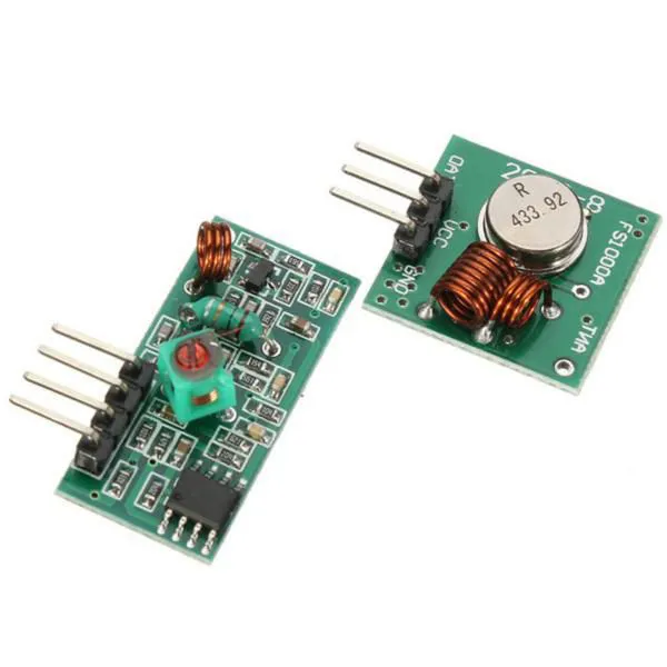
In our tutorial I will supply both the transmitter and receiver with 5V, each with its own power supply (which is essentially the ESP32 connected to it). I am using 17cm (170mm) single core wire as antenna for both the receiver and transmitter. The reason for ~17cm is it it representes a quarter of the wavelenght of 433Mhz (which is ~69cm), which is said to be a “sweet spot” for communication.
I am using a ESP32-C3 super mini as the transmitter microcontroller, it has some details that one needs to observe. Some important details regarding the transmitter ESP32-C3 Super mini:
- You have to select “Nologo ESP32C3 Super mini” on Arduino IDE
- There is a nedd to define the i2c pins on your sketch, since they are not 4 and 5 anymore. On the Super mini they are 6 and 7, so do “Wire.begin(6, 7);”
- HDC1080 address is 0x40, there is no need to change that. But in case your sketch does not work may be due to a different sensor address. In this case you shold first use an i2c scanner code like this one and afterwards change the address in “hdc1080.begin(0x40);”.
As for the receiver I am using a Xiao ESP32-C6 seen here, which requires that you call its pins as (for example) “D2” instead of “2”. Besides that there is nothing special on the receiving end that you need to worry about. Actually you could use (roughly) the same sketchs with any type of Arduino you like, not necessarily with ESP32 only.
Hardware
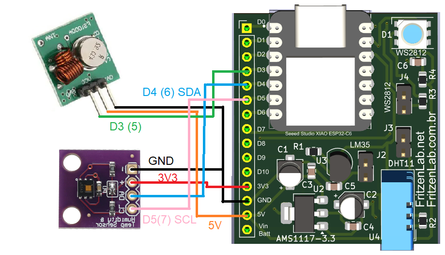
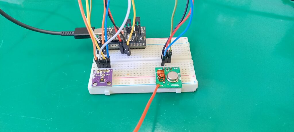
This time our hardware connections will be a bit different, more complete and complex. This is since we have two ends of the experiment: transmitter and receiver. Between the two the transmitter is a bit bigger. It is solely eue to the fact that there is the HDC1080 temperature sensor and the 433MHz transmitter to connect. This is your way of learn and use 433MHz radio.
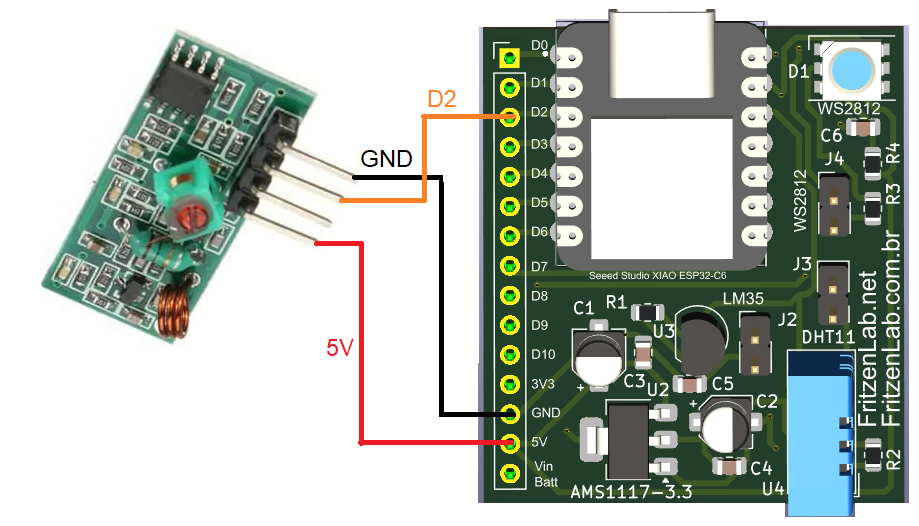
Receiver on the other end only needs a wire between the 433MHz module and the ESP32. Look below for both diagrams.
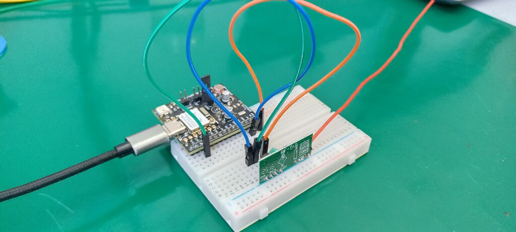
I assembled both circuits on breadboards, one for each. There are a coupl of pictures below.
Code/firmware
There is the need for a library to write and read to these 433MHz modules. I searched the internet and found one called “RC-Switch”, here. It harnessess the power of interrupts in order to make the 433MHz readings (receiver end). We also need to read the HDC1080 temperature and humidity sensor, something we already did in a previous blog post. I put both codes together and came up with the transmitter code below:
// modified by Clovis Fritzen in 03/22/2025, FritzenLab.net
/**************************************************************************************

This is example for ClosedCube HDC1080 Humidity and Temperature Sensor breakout booard

Initial Date: 07-Jun-2017

Hardware connections for Arduino Uno:
VDD to 3.3V DC
SCL to A5
SDA to A4
GND to common ground

Written by AA for ClosedCube

MIT License

**************************************************************************************/

#include <Wire.h>
#include "ClosedCube_HDC1080.h"
#include <RCSwitch.h>

RCSwitch rfsense = RCSwitch();

int analog;
ClosedCube_HDC1080 hdc1080;

void setup()
{
	Serial.begin(9600);
	Serial.println("ClosedCube HDC1080 Measurement Resolutions Arduino Test");
        Wire.begin(6, 7); // info from https://forum.arduino.cc/t/change-i2c-sda-and-scl-pin-of-arduino-and-trinket-m0/957719/4
	hdc1080.begin(0x40);

	Serial.print("Manufacturer ID=0x");
	Serial.println(hdc1080.readManufacturerId(), HEX); // 0x5449 ID of Texas Instruments
	Serial.print("Device ID=0x");
	Serial.println(hdc1080.readDeviceId(), HEX); // 0x1050 ID of the device

	/*printTandRH(HDC1080_RESOLUTION_8BIT, HDC1080_RESOLUTION_11BIT);
	printTandRH(HDC1080_RESOLUTION_11BIT, HDC1080_RESOLUTION_11BIT);
	printTandRH(HDC1080_RESOLUTION_14BIT, HDC1080_RESOLUTION_11BIT);
	printTandRH(HDC1080_RESOLUTION_8BIT, HDC1080_RESOLUTION_14BIT);
	printTandRH(HDC1080_RESOLUTION_11BIT, HDC1080_RESOLUTION_14BIT);
	printTandRH(HDC1080_RESOLUTION_14BIT, HDC1080_RESOLUTION_14BIT);*/

  rfsense.enableTransmit(5);
  delay(1000);

}

void loop()
{
  //printTandRH(HDC1080_RESOLUTION_11BIT, HDC1080_RESOLUTION_11BIT);
  rfsense.send(hdc1080.readTemperature()*100, 12);
  delay(1000);
}

void printTandRH(HDC1080_MeasurementResolution humidity, HDC1080_MeasurementResolution temperature) {
	hdc1080.setResolution(humidity, temperature);

	HDC1080_Registers reg = hdc1080.readRegister();
	//printRegister(reg);

	Serial.print("T=");
	Serial.print(hdc1080.readTemperature());
	Serial.print("C, RH=");
	Serial.print(hdc1080.readHumidity());
	Serial.println("%");
}

void printRegister(HDC1080_Registers reg) {
	Serial.print("Measurement Resolution: T=");
	Serial.print(reg.TemperatureMeasurementResolution, BIN);
	Serial.print(" (0=14 bit, 1=11 bit)");

	Serial.print(" RH=");
	Serial.print(reg.HumidityMeasurementResolution, BIN);
	Serial.println(" (00=14 bit, 01=11 bit, 10=8 bit)");
}
Receiver code then uses interrupts to harness the power of the 433MHz module. It has a function called “rfsense.getReceivedValue()” to do so. Full code for receiving end is below:
//Programa: Circuito Receptor RF 433 MHz
//Autor: Arduino e Cia

#include <RCSwitch.h>

RCSwitch rfsense = RCSwitch();

void setup()
{
  Serial.begin(9600);
  //Pino do led
  //pinMode(6, OUTPUT);

  //interrupt pin defined with help from https://forum.arduino.cc/t/solved-rf433-transmitter-on-esp32-rcswitch/681005
  rfsense.enableReceive(digitalPinToInterrupt(D2));

  Serial.println("Receptor RF 433 MHz");
  Serial.println("Iniciando.....................");
  delay(2000);
}

void loop()
{
  if (rfsense.available())
  {
    //Verifica o valor recebido pelo receptor
    //int valor = rfsense.getReceivedValue();
    float value = rfsense.getReceivedValue() / 100.0;
    Serial.println(value);

  }
  rfsense.resetAvailable();

}
Testing/final thoughts
Upon supplying both emitter and receiver with USB C power, you should look at the serial monitor fo the Arduino IDE for the receiver. A temperature value in degrees Celsius should start being printed to the screen. It should have two decimal places, something I had to use a “*100” on the emitter and “/100” on the receiver to make work.
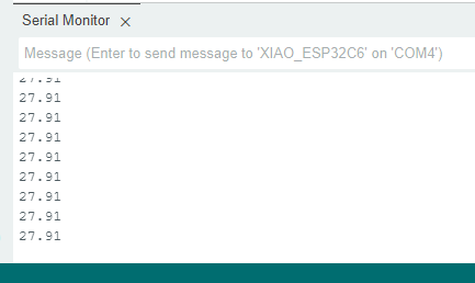
In my case the temperature being shown was 27.91 degrees Celsius, pretty high for the fall in my region. I tested the set inside home between walls, in a 10+ meters distance. It works without interruption. It is said that such sets work on 40+ meters distance, but I did not test it going so far.
I made a full video of the system working for you to have and idea and replicate. Enjoy and please comment below your questions. If you want to buy the HDC1080 click here, and to buy the 433MHz kit click here.


Pingback: Youtube subscribers counter with ESP32 - FritzenLab electronics