Let’s program and test the The easiest temperature sensor with microPython, using a Raspberry Pi Pico 2 as the microcontroller. I have showed you how to use the DS18b20 before here, that time with ESP32 and Arduino code. This time we are using microPython, since I am writing a series of tutorias with it.
DS18b20 is a temperature sensor whose communication protocol to the microcontroller is called one wire. It literally only needs one wire to send temperature values to the Pi Pico 2, besides 3V3 and GND. Its datasheet is here, indicating a measuring range of -55ºC to +125ºC. Now an accuracy of +/-0.5ºC is obtained in the range os -10ºC to +85ºC.
One important parameter the datasheet brings us is the measurement settling time. Means it takes time for a measurement to be “ready” to be used. For you to have an idea, a 9 bit measurement takes ~94ms. While for a 12 bit measurement it takes 750ms. So we must account for that in our code; more on that later.
Hardware/schematic
As usual here in the blog, the schematic diagram for the experiments is very simple and clean. In today’s case all we need is a digital IO pin; that’s pin 26 for the one wire communication with DS18b20. Pin 26 also has the function ADC0 (analog input), which we will not be using.
You can pick literally any IO pin of your choice, since the one wire protol is a software-defined thing.We will be supplying voltage to the Pi Pico 2 via the micro USB cable connector. It takes 5V and converts to the necessary 3.3V for the DS18b20.
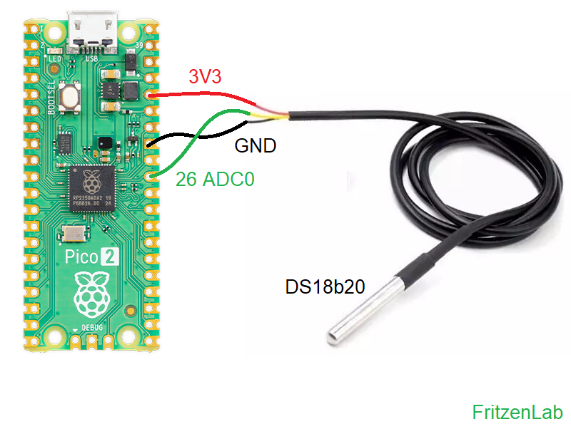
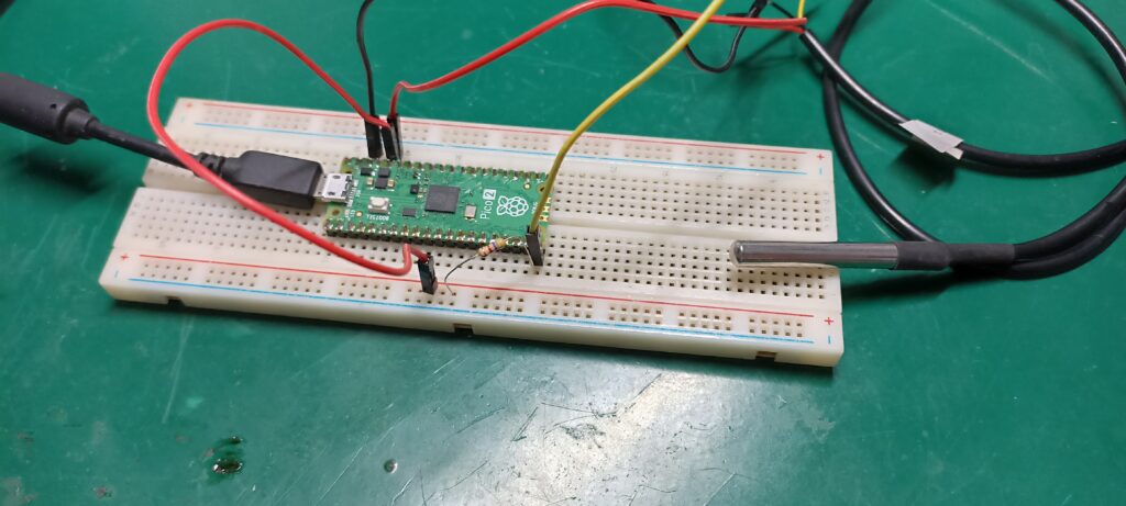
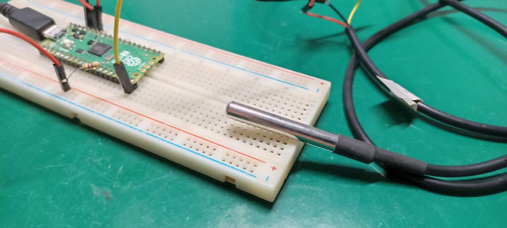
See below the assembly of the DS18b20 (The easiest temperature sensor) with the Pi Pico 2 on a breadboard. One thing I did not represent in the schematic diagram above (but is necessary) is a pull up resistor. There is a need for a 4700 Ohm resistor between the signal pin (yellow cable) and VCC (red cable).
Code/firmware
According to the DS18b20 datasheet linked above, for a 12 bit reading the sensor takes 750ms (0.75 seconds) to read. I found that to be too slow, so I wanted to decrease resolution to make the sensor read faster. I found this resource explaining how to change sensor resolution, then changed mine to 10 bit doing:
ds_sensor.write_scratch(rom, b'\x00\x00\x3f') # set sensor resolution to 10 bitI then needed an example code to work my own code on top of. I ended up selection this article from RandomNerdTutorials, a very complete one. I modified the example code a lot, for example removing the sleep() functions and making my code non-blocking. I also changed the sensor reading resolution (as seen above) and put an LED to blink in parallel with it all.
Now the library “ds18x20” necessary to run the example code already comes pre-installed with Thonny IDE. I made the line below to import all I needed for this example to run:
import machine, onewire, ds18x20, timeFull code is below. Save the file inside the Pi Pico 2 as “main.py” and click the green arrow (“Run current script (F5)”).
# Loosely based on code from https://RandomNerdTutorials.com/raspberry-pi-pico-ds18b20-micropython/

import machine, onewire, ds18x20, time

ds_pin = machine.Pin(26)
ds_sensor = ds18x20.DS18X20(onewire.OneWire(ds_pin))

roms = ds_sensor.scan()
print('Found DS devices: ', roms)
initialtime= time.ticks_ms() #https://docs.micropython.org/en/latest/library/time.html
timeds18b20= time.ticks_ms()
timeled= time.ticks_ms()

onboardled= machine.Pin(25, machine.Pin.OUT)

while True:
    #currenttime= time.ticks_ms() #Every time it passes here, gets the current time

    if time.ticks_diff(time.ticks_ms(), timeds18b20) > 200: # this IF will be true every 200 ms
            timeds18b20= time.ticks_ms() #update with the "current" time

            ds_sensor.convert_temp() #only 200ms conversion time is necessary when sensor is read in 10 bit

    if time.ticks_diff(time.ticks_ms(), initialtime) > 1000: # this IF will be true every 3000 ms
            initialtime= time.ticks_ms() #update with the "current" time

            for rom in roms:
                #print(rom) # "raw"
                ds_sensor.write_scratch(rom, b'\x00\x00\x3f') # set sensor resolution to 10 bit
                tempC = ds_sensor.read_temp(rom)
                #tempF = tempC * (9/5) +32
                print('temperature (ºC):', "{:.2f}".format(tempC))
                #print('temperature (ºF):', "{:.2f}".format(tempF))
                #print()

    # statement below just blinks an LED
    if time.ticks_diff(time.ticks_ms(), timeled) > 200: # this IF will be true every 200 ms
        timeled= time.ticks_ms() #update with the "current" time

        if onboardled.value() == 0:
            onboardled.value(1)
        else:
            onboardled.value(0)
End result
I have commented the Fahrenheit conversion code but you can just uncomment it. As is the code just shows Celsius temperature. I separated the code in three IF statements:
- The first reads the sensor every 200ms
- The second fetches the read value from the sensor and shows it on print()
- The third just blinks and LED
There is a video below illustrating everything necessary to make this example run, enjoy!. If you wan to buy the DS18b20 from my affiliate link, click here.


Pingback: MPU-9255 Accelerometer and gyroscope - FritzenLab electronics