I will show you how to read the super easy LM35 temperature sensor with microPython. We will use one analog input of the Raspberry Pi Pico 2 and Thonny IDE software. Our Pi Pico 2 has three analog input pins (ADC0-2, pins 26-28) which are 12 bit in resolution. However for some reason this 12 bit value is transformed into a 16 bit one.
So instead of receiving values between 0 and 4095, we read integers between 0 and 65535. Of course there will not be 65535 “voltage steps”, but only 4095 inside. I will be showing you how to read an analog sensor using one input, the LM35 temperature one. LM35’s datasheet is here and states its output is 10mV (0.01V) per degree Celsius.
That means an expected output of 250mV for a 25ºC environment. Or similarly a temperature of 31ºc for a 310mV output.
Hardware/connections
As it is traditional here on the blog, schematic diagrams are always simple to follow, nothing complex. Today’s article contains only a LM35 sensor, then a single wire is necessary to carry all information required. We are connecting LM35’s output to pin 26 of the Pi Pico 2, which is ADC0.
Besides that, all that is necessary are pin 3V3 and GND to supply the sensor. You can check the Pi Pico 2’s pinout here.
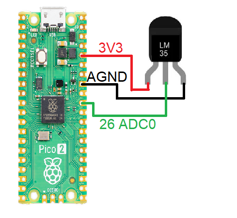
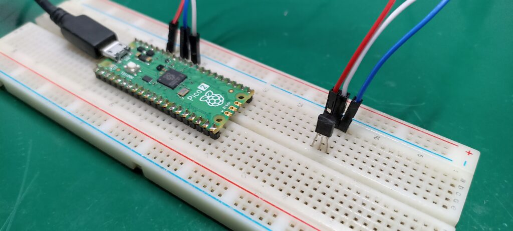
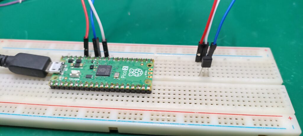
There are two pictures below showing my setup, I put everything on a 830 points breadboard. Red wire is 3V3, blue is GND and white is analog signal to pin 26. Super easy LM35 comes in a couple of different cases, the one I have is plastic TO-92, which is not easy to attach to nothing. But our objective here is to test the sensor, not attach it to anything.
Coding/firmware
I used this trusted reference for coding example. That’s for the analog reading part only, since the time management part was made by myself. I created a way of implementing a non-blocking code, similar to the concept of “BlinkWithoutDelay” present in Arduino IDE examples.
There is essentially a variable keeping track of the “old” or “previous” time, then a comparison to the current time (“time.ticks_ms()”). When 1000 milliseconds have passed (1 second) the IF statement gets true and executes an analog reading. All the other times the code verifies that IF (and 100ms have not passed), nothing is executed and the code does not get stuck anywhere.
That means you can implement many other things over this code, like a 7 segment LED display for example. Or even a LCD and some buttons for create a HMI (human-machine interface). Your creativity is the only limiting factor here. Full code is below, notice that we are importing only three packages: “Pin” for IO, “ADC” for analog and “time” for tracking.
# with ideas from: https://randomnerdtutorials.com/raspberry-pi-pico-analog-inputs-micropython/
from machine import Pin, ADC
import time

initialtime= time.ticks_ms() #https://docs.micropython.org/en/latest/library/time.html
LM35 = ADC(Pin(26)) #ADC0


while True:

    currenttime= time.ticks_ms() #Every time it passes here, gets the current time
    if time.ticks_diff(time.ticks_ms(), initialtime) > 1000: # this IF will be true every 1000 ms
        initialtime= time.ticks_ms() #update with the "current" time

        LM35raw = LM35.read_u16() # read value, 0-65535 across voltage range 0.0v - 3.3v
        # line below converts from 16bit to volts, then rounds it to 3 places then
        # multiplies by 100 to convert from milivolts to degrees Celsius
        LM35C= round((LM35raw * 3.3 / 65535),3)*100
        print(LM35C, end= "")
        print(" C")
End result
Type the code above in a new file in Thonny IDE, save it to the Pi Pico 2 as “main.py”. Now click the green arrow at the top of the screen (“Run current script (F5)”). You should start seeing temperature values being printed in the shell at the bottom of the screen.
Look at the video below, there is a complete explanation of everything. From schematics to code to the IDE. The Super easy LM35 is just a walk in the park to control and read.


Pingback: LCD display with micropython - FritzenLab electronics
Pingback: ESP32-C3 internal temperature sensor with microPython - FritzenLab electronics
Pingback: Analog input readings with ESP32 - FritzenLab electronics