Let’s gather all our knowledge and become a master of analog voltages with microPython. We will be using a MCP4725 DAC (digital to analog converter) paired with a Raspberry Pi Pico 2 microcontroller. There is going to exist a LCD display (to show voltage and a bit of text), model GC9A01 which is a 240×240 LCD SPI one. We have seen about this display here (with Arduino UNO) and here before.
MCP4725 is a 12 bit one channel digital to analog converter (DA) whose datasheet is here. This integrated circuit from Microchip is capable of creating (or generating) analog voltage when commanded via i2c port. It works from 2.7V to 5.5V and at i2c speeds of 100kbps, 400kbps or 3.4Mbps. It can then generate voltages at the will or command of our Raspberry Pi Pico 2 with microPython code.
We will also need a multimeter for this experiment. Does not need to be a fancy one, since we will be measuring voltages up to 3.3V only. In fact any (really, any) multimeter can measure such voltages for us. I have a HM2080 and a HM2010 at my disposal, which are from this Brazilian brand called Hikari.
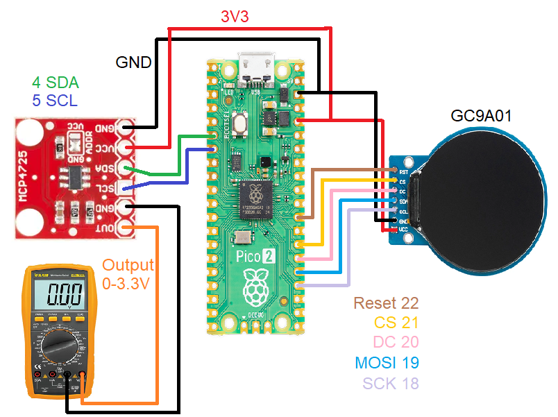
Schematic diagram
Today’s schematic diagram is a bit more fancy of if you want to call it, “complicated”. It uses both i2c and SPI ports along with 3V and GND from the Pi Pico 2. Power supply comes via the micro USB cable that connects the Pi Pico 2 to the computer. Notice that I always color-code my drawings so that you don’t get lost in so many wires.
This is the first step for you to become a master of analog voltages with Pi Pico 2 and microPython.
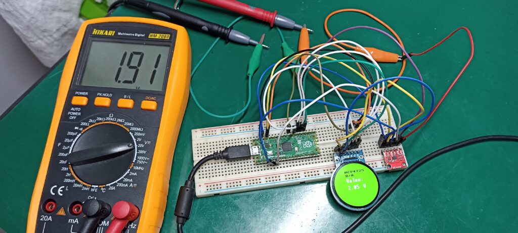
A 830 point breadboard is enough to house the Pi Pico 2, GC9A01 display and MCP4725 DA converter. Also look at the multimeter over the bench and to the left of the breadboard. I used alligator clips to connect the multimeter leads to the MCP4725 output wires.
Firmware/code
Library to interface the MCP4725 in microPython to the Pi Pico 2 is not mine, I found it here. What I actually did was heavily modify it to fit my needs, as for example add code for the GC9A01 LCD display. I also implemented non-blocking code, meaning I am not using time.sleep() that halts the code. Instead I keep track of time with “time.ticks_ms()” and only enter my main function (an IF statement) every 3000ms (3 seconds).
You have to save a file called “mcp4725.py” to the Pi Pico 2 (inside the microcontroller, not in your computer) using Thonny IDE. Content of this file is in the Github linked in the paragraph above. Besides that you have to create another file called “main.py” and also save it to the Pi Pico 2. Content of this file (and main code for this article) is below.
On your way to become a master of analog voltages with Pi Pico 2 and microPython.
# MCP4725 library: https://github.com/wayoda/micropython-mcp4725
from machine import Pin, SPI
import gc9a01py as gc9a01
from machine import I2C
import time
import mcp4725
from mcp4725 import MCP4725, BUS_ADDRESS
import sys
import uselect
i2c = I2C(id=0, scl=5, sda=4, freq=400_000)
initialtime= time.ticks_ms() #https://docs.micropython.org/en/latest/library/time.html
def main():
spi = SPI(0, baudrate=60000000, sck=Pin(18), mosi=Pin(19))
tft = gc9a01.GC9A01(
spi,
dc=Pin(20, Pin.OUT),
cs=Pin(21, Pin.OUT),
reset=Pin(22, Pin.OUT),
backlight=Pin(1, Pin.OUT),
rotation=90)
tft.fill(gc9a01.GREEN) # fill screen in green
initialtime= time.ticks_ms() #https://docs.micropython.org/en/latest/library/time.html
dac=mcp4725.MCP4725(i2c,mcp4725.BUS_ADDRESS[0])
# from fonts import vga1_8x8 as font
from fonts import vga2_8x8 as font1
# from fonts import vga1_8x16 as font
from fonts import vga2_8x16 as font2
# from fonts import vga1_16x16 as font
# from fonts import vga1_bold_16x16 as font
# from fonts import vga2_16x16 as font
from fonts import vga2_bold_16x16 as font3
# from fonts import vga1_16x32 as font
# from fonts import vga1_bold_16x32 as font
# from fonts import vga2_16x32 as font
from fonts import vga2_bold_16x32 as font
# lines below are the ones to read user keyboard in Thonny IDE
spoll=uselect.poll()
spoll.register(sys.stdin,uselect.POLLIN)
def read1():
return(sys.stdin.read(4) if spoll.poll(0) else None)
while True:
try:
currenttime= time.ticks_ms() #Every time it passes here, gets the current time
if time.ticks_diff(time.ticks_ms(), initialtime) > 3000: # this IF will be true every 3000 ms
initialtime= time.ticks_ms() #update with the "current" time
c = read1() # verify whether user typed a number
if c != None:
print(c)
d= float(c)
if d > 3.3:
d = 0
valuetowrite= int(d * 4095 / 3.3)
dac.write(valuetowrite)
#showonscreen= str(round((valuetowrite/4095 * 3.3), 3))
showonscreen= str(round(d, 3))
tft.text(font, showonscreen, 70, 120, gc9a01.WHITE, gc9a01.GREEN)
pass
#dac.read()
tft.text(font3, "MCP4725", 70, 40, gc9a01.BLACK, gc9a01.GREEN)
tft.text(font3, "D/A", 70, 60, gc9a01.BLACK, gc9a01.GREEN)
tft.text(font, "Value:", 70, 80, gc9a01.WHITE, gc9a01.GREEN)
tft.text(font, " V", 140, 120, gc9a01.WHITE, gc9a01.GREEN)
#print(user)
except OSError as e:
print('Failed reception')
# If any function above does not work
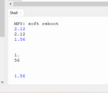
main()After creating and populating both “.py” files, in Thonny IDE click the green arrow (“run current script (F5)”). Observe the bottom part of the screen, this is where the shell is and also where you are going to type the desired voltage. What you will do is type a voltage between 0.00 and 3.30 (up to two decimal places), then hit “ENTER” in you keyboard. Look at an example in the image below.
Final result
In blue in the image above are the values you type, while in black is the answer from the board (like an acknowledgment). Note that there was a bug, there is a “1.” and then in the line below “56”, that happened sometimes to me and is not normal/correct.
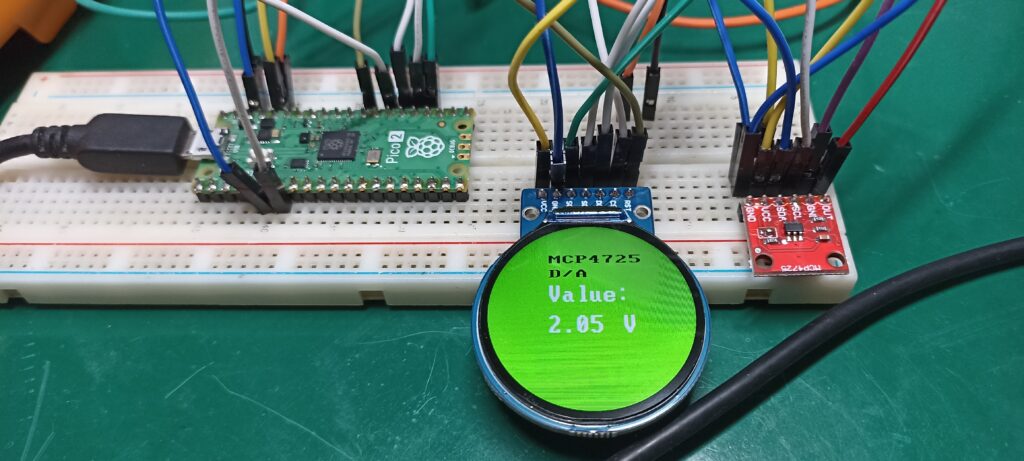
Connecting a multimeter in voltage mode to the “OUT” and “GND” pins of the MCP4725, you have to observe a voltage. That voltage has to be close to the one you just typed in the Thonny IDE shell. I made a video illustrating all we have talked about in this blog post, enjoy!.


