In today’s post we will get to master the round display GC9A01 with microPython, using a Raspberry Pi Pico 2 as the controller. We will implement such circuit on a breadboard, but nothing stops you from making a more permanent assembly. That would involve soldering and prototyping skills, as well as (maybe) 3D printing and NC machines, at your will.
Display GC9A01 is a 240×240 pixels, 262,144 RGB colors and 3.3V supply display (datasheet here). It communicates with microcontrollers via SPI protocol/port, since it has its own controller internally. We have seen that display being used before here, that time with an Arduino UNO and the Arduino IDE software.
As part of the experiment we will be reading the HDC1080 temperature and humidity sensor from this post, then showing temperature and humidity on our GC9A01 display. Said sensor uses i2c communication protocol while the display uses SPI, so our Raspberry Pi Pico 2 will be rather busy at work.
Hardware and assembly
As usual here in the blog, the schematic diagram for this experiment is simple, but this time not so simple. Since we are using a sensor and a display, both i2c and SPI ports will be in use. Besides that our power supply comes via micro-USB connection, along with serial communication with the computer for data visualization.
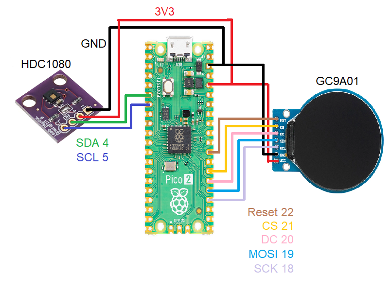
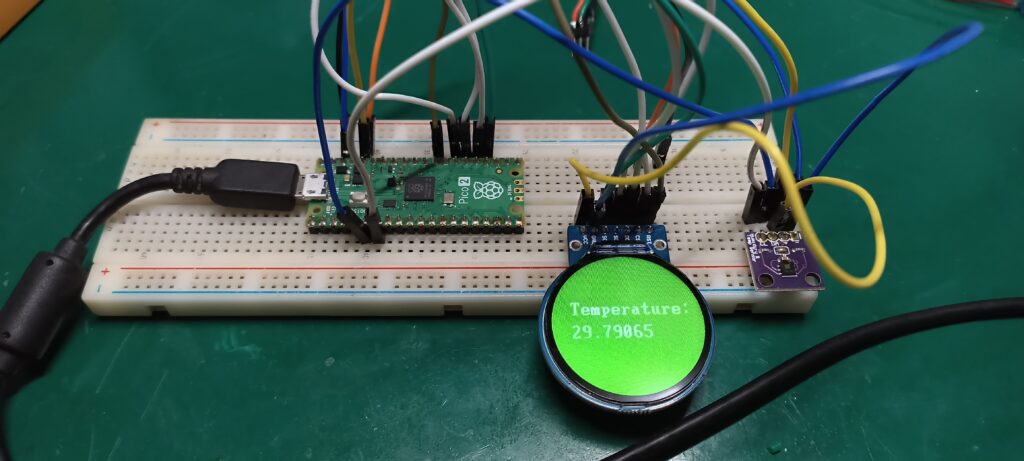
Below there are two pictures showing the prototype assembled on a breadboard. Please don’t mind the messy cables.

Firmware/code
I searched the internet for a library for the GC9A01 round LCD display with microPython. Ended up finding this one, along with examples of utilization of things like fonts and shapes. Regarding the HDC1080 temperature and humidity sensor, we have seen it before here, so I used the code I already had. Remember – master the round display GC9A01 with microPython.
There are a couple of files you have to save into your Raspberry Pi Pico 2 (or any other board that runs microPython): first is the “hdc1080.py” that you can copy from here and past inside the Pi Pico 2. Next there are a couple of files from the Github linked above and here, inside the “lib” folder there is the “gc9a01py.py” that needs to be copied to inside the Pi Pico 2.
Inside the folder “fonts/romfonts” copy all files and paste inside your Pi Pico 2. Be sure to create a folder called “fonts”. Inside the “examples” folder there is a file called “chars.py” which I used to create my code below.
I ended up developing a code that show some text (“HDC1080 sensor”), temperature in degrees Celsius and humidity in percentual. Here is the complete code. Notice that this code goes to the file “main.py” INSIDE THE Raspberry Pi Pico 2, not saved into your computer.
from machine import Pin, SPI
import gc9a01py as gc9a01
from machine import I2C
import time
import dht
from hdc1080 import HDC1080

i2c = I2C(0)
hdc = HDC1080(i2c)


initialtime= time.ticks_ms() #https://docs.micropython.org/en/latest/library/time.html
hdc.config(humid_res=14, temp_res=14, mode=0, heater=0)

if hdc.check():
    print(f"Found HDC1080 with serial number {hdc.serial_number()}")

def main():

    spi = SPI(0, baudrate=60000000, sck=Pin(18), mosi=Pin(19))
    tft = gc9a01.GC9A01(
        spi,
        dc=Pin(20, Pin.OUT),
        cs=Pin(21, Pin.OUT),
        reset=Pin(22, Pin.OUT),
        backlight=Pin(1, Pin.OUT),
        rotation=90)

    tft.fill(gc9a01.GREEN)
    initialtime= time.ticks_ms() #https://docs.micropython.org/en/latest/library/time.html
    sensor = dht.DHT11(Pin(15))

    # from fonts import vga1_8x8 as font
    from fonts import vga2_8x8 as font1
    # from fonts import vga1_8x16 as font
    from fonts import vga2_8x16 as font2
    # from fonts import vga1_16x16 as font
    # from fonts import vga1_bold_16x16 as font
    # from fonts import vga2_16x16 as font
    from fonts import vga2_bold_16x16 as font3
    # from fonts import vga1_16x32 as font
    # from fonts import vga1_bold_16x32 as font
    # from fonts import vga2_16x32 as font
    from fonts import vga2_bold_16x32 as font

    while True:
        try:
            currenttime= time.ticks_ms() #Every time it passes here, gets the current time
            if time.ticks_diff(time.ticks_ms(), initialtime) > 3000: # this IF will be true every 2000 ms
                initialtime= time.ticks_ms() #update with the "current" time

                print(f"{hdc.temperature()} C, {hdc.humidity()} RH")
                temp1= str(round(hdc.temperature(),2))
                hum1= str(round(hdc.humidity(),2))
                tft.text(font3, "HDC1080", 70, 40, gc9a01.BLACK, gc9a01.GREEN)
                tft.text(font3, "sensor", 70, 60, gc9a01.BLACK, gc9a01.GREEN)
                tft.text(font, "Temperature:", 30, 80, gc9a01.WHITE, gc9a01.GREEN)
                tft.text(font, temp1, 70, 120, gc9a01.WHITE, gc9a01.GREEN)
                tft.text(font, " C", 150, 120, gc9a01.WHITE, gc9a01.GREEN)
                tft.text(font2, "Humidity:", 80, 160, gc9a01.BLACK, gc9a01.GREEN)
                tft.text(font2, hum1, 100, 180, gc9a01.BLACK, gc9a01.GREEN)
                tft.text(font2, " %", 140, 180, gc9a01.BLACK, gc9a01.GREEN)

        except OSError as e:
            print('Failed reception')
            # If the Pi Pico 2 does not receive the measurements from the sensor


main()
End result
Now master the round display GC9A01 with microPython. Save the file “main.py” with the above code and click the green arrow “Run current script (F5)”. You should see in Thonny IDE a screen like the one below. You also should look at the display itself and see an image similar to the one below.
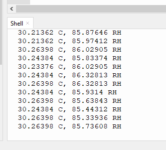
Screen will update every three (3) seconds with a new temperature and humidity, if everything is working as it should. If not, I recommend you to have a look at the display and sensor wiring. You should also test the HDC1080 sensor by itself using the code and article linked above.
I present you with a video of the system working, showing a bit of the coding in Thonny IDE. Also showing the breadboard view for your comparison and benchmark. Enjoy and please comment your questions in the form below.


Pingback: Become a master of analog voltages with microPython - FritzenLab electronics