Today we will connect and test a Thermocouple with MAX6675 in microPython, using a Raspberry Pi Pico 2 as the controller. We will program using the Thonny IDE software, as already seen in here. Thermocuple is a temperature sensor comprised of two different metals soldered together. Such setup is capable of generating a couple of microvolts (uV) with temperature variations.
We have tested the MAX6675 controller with Arduino UNO before, in this post. At that time we used Arduino code in the Arduino IDE. I have decided to bring such hardware setup back, in order to excercise my microPython skills. MAX6675’s datasheet is here , the chip features a range of measurements of 0ºC to 700ºC with 8 LSB. It is capable of a 0.25ºC step.
It reads K-type thermocouples and has cold-junction compensation, while offering a SPI-like communication port. The objective of this article is to be able to read temperature in degress Celsius and show it on computer screen, on Thonny IDE’s shell.
Hardware
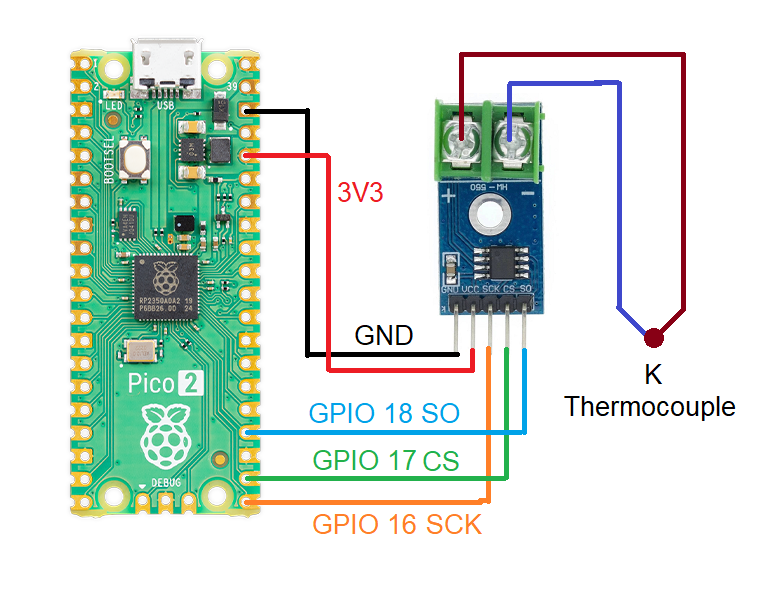
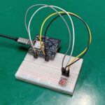
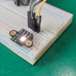
As with many experiments and articles here on the blog, the schematic diagram (connections) is very simple and straightforward. Five (5) wires are necessary to extract readings from the MAX6675 chip: +3.3V, GND, SCK, SO, CS. According to its datasheet, the chip can be supplied with voltages from +3V to +5.5V. In our previous article we had it working with 5V, while today this will be done with 3.3V.
Just a heads up regarding the usage of Raspberry Pi Pico 2, you are free to use any hardware you want that runs microPython. The likes of ESP32, micro:bit, Arduino Nano RP2040, Arduino Nano 33, etc will all work. Even (and specially) the original Pi Pico (RP2040) will do.
Firmware/code
Open your Thonny IDE, create a new file and paste the code below into it. When asked you save as “max6675.py” INSIDE THE PI, not in the computer.
# code from https://github.com/BetaRavener/micropython-hw-lib/tree/master/MAX6675

import time


class MAX6675:
    MEASUREMENT_PERIOD_MS = 220

    def __init__(self, sck, cs, so):
        """
        Creates new object for controlling MAX6675
        :param sck: SCK (clock) pin, must be configured as Pin.OUT
        :param cs: CS (select) pin, must be configured as Pin.OUT
        :param so: SO (data) pin, must be configured as Pin.IN
        """
        # Thermocouple
        self._sck = sck
        self._sck.low()

        self._cs = cs
        self._cs.high()

        self._so = so
        self._so.low()

        self._last_measurement_start = 0
        self._last_read_temp = 0
        self._error = 0

    def _cycle_sck(self):
        self._sck.high()
        time.sleep_us(1)
        self._sck.low()
        time.sleep_us(1)

    def refresh(self):
        """
        Start a new measurement.
        """
        self._cs.low()
        time.sleep_us(10)
        self._cs.high()
        self._last_measurement_start = time.ticks_ms()

    def ready(self):
        """
        Signals if measurement is finished.
        :return: True if measurement is ready for reading.
        """
        return time.ticks_ms() - self._last_measurement_start > MAX6675.MEASUREMENT_PERIOD_MS

    def error(self):
        """
        Returns error bit of last reading. If this bit is set (=1), there's problem with the
        thermocouple - it can be damaged or loosely connected
        :return: Error bit value
        """
        return self._error

    def read(self):
        """
        Reads last measurement and starts a new one. If new measurement is not ready yet, returns last value.
        Note: The last measurement can be quite old (e.g. since last call to `read`).
        To refresh measurement, call `refresh` and wait for `ready` to become True before reading.
        :return: Measured temperature
        """
        # Check if new reading is available
        if self.ready():
            # Bring CS pin low to start protocol for reading result of
            # the conversion process. Forcing the pin down outputs
            # first (dummy) sign bit 15.
            self._cs.low()
            time.sleep_us(10)

            # Read temperature bits 14-3 from MAX6675.
            value = 0
            for i in range(12):
                # SCK should resemble clock signal and new SO value
                # is presented at falling edge
                self._cycle_sck()
                value += self._so.value() << (11 - i)

            # Read the TC Input pin to check if the input is open
            self._cycle_sck()
            self._error = self._so.value()

            # Read the last two bits to complete protocol
            for i in range(2):
                self._cycle_sck()

            # Finish protocol and start new measurement
            self._cs.high()
            self._last_measurement_start = time.ticks_ms()

            self._last_read_temp = value * 0.25

        return self._last_read_temp
Now open another blank file in Thonny IDE and paste the code below, which is our “main.py” code, where the magic happens. Save it INSIDE THE PI, not in the computer.
# This code was modified by Clovis Fritzen, based on https://github.com/BetaRavener/micropython-hw-lib/tree/master/MAX6675
from max6675 import MAX6675
from machine import Pin
import time

so = Pin(18, Pin.IN)
sck = Pin(16, Pin.OUT)
cs = Pin(17, Pin.OUT)

max = MAX6675(sck, cs , so)
initialtime= time.ticks_ms() #https://docs.micropython.org/en/latest/library/time.html

while True:
    currenttime= time.ticks_ms() #Every time it passes here, gets the current time
    if time.ticks_diff(time.ticks_ms(), initialtime) > 1000: # this IF will be true every 1000 ms
        initialtime= time.ticks_ms() #update with the "current" time

        print(max.read())
Now press the green arrow on top of the screen (“Run current script (F5)”) and observe the shell at the bottom of the screen.
End result
What you will see is a number being printed every 1000ms (one second), representing temperature in degrees Celsius.
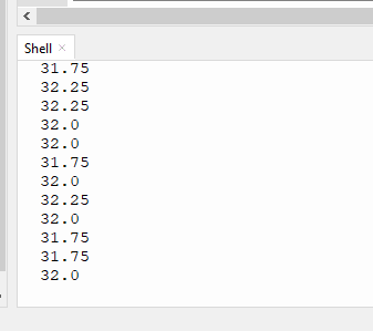
If you don’t see a screen similar to the one above, have a look at your circuit (pin numbers and positions), whether the physical connection corresponds to the pins assigned in code (as seen below).
so = Pin(18, Pin.IN)
sck = Pin(16, Pin.OUT)
cs = Pin(17, Pin.OUT)
Also check whether you named both files right, “max6675.py” and “main.py” and saved both IN THE DEVICE, not in the computer. I made a video to illustrate today’s test, enjoy:

Leave a Reply