In today’s post we will read theBH1750 easy light level sensor with microPython, using the Raspberry Pi Pico 2 with RP2350. We have seen and tested this sensor before here, that time with an ESP32-C6. This time around we will re-test it with microPython and a Raspberry Pi Pico 2.
This neat little sensor BH1750 (datasheet here) reads light level in Lux up to 65535, which is not up there with the brightest of the suns. This is why I would recommend it to “indoor” use, like in projects that are not exposed to the elements. I have choosen to program this tutorial in microPython using the Pi Pico 2 because I am creating a course on that subject, so it looked like the natural choice.
Hardware
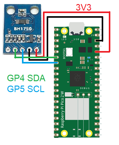
Physical connections for this project are again very simple, all you need ist to connect the BH1750 to the Raspberry Pi Pico 2. That is done via i2c port, so all you need is SDA, SCL, +3V3 and GND. I2c port in the RP2350 can assume a bunch of different positions (configurable in your code), but the standard one is pins 4 and 5.
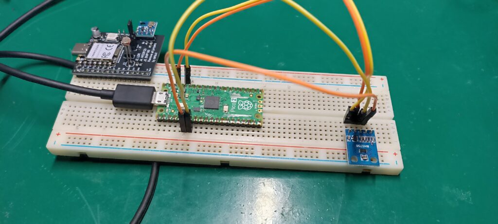
Power and communications comes via USB micro cable connected directly into the Pi Pico 2. You can either use a breadboard for the connections or solder everything directly into each other, using 22 AWG wire (for example). Below there is the schematic used and also a picture of the real deal, in my bench.
Firmware/code
BH1750 code is not mine and was found on this Github, consists of four “.py” files necessary to interface with the sensor. I modified the code enough to fit my needs, so that it is not “original” anymore. One of the things I removed was the time (hours, minutes, seconds) being printed on the shell for every reading, did not find it necessary or useful.
The way the code works is it makes a reading every time a conversion time reaches its value, which is calculated internally by the sensor itself. That happens inside the file “bh1750.py” in the function “get_conversion_cycle_time”, a time in milisseconds is returned for the main function and applied as delay time.
There is also a “protection” that does not allow new values while the value just read is equal to the previous one. Another nice function of this code is the normalized percentual, it shows the percentual the current reading represents of the maximum ever read. All of that to show current quality values in Lux and also the maximum ever read.
All code is available on my Github here. There are also in the link pictures I used in this article, all for you to download and use.
I had to check and change the line below with my board’s i2c information, on “main.py”. Value “id=0” means I am using i2c0, with SCL on pin 5 and SDA on pin 4. Bus frequency is 400Khz.
i2c = I2C(id=0, scl=5, sda=4, freq=400_000)Testing
I made a video explaining the assembly and coding, as well as the Lux levels presented. I briefly touch on the BH1750’s (easy light level sensor) datasheet and shell information being relayed. Enjoy the video and please comment your questions on the form below this article.


Pingback: AS7341 RGB and IR light sensor - FritzenLab electronics