Let’s get to know how to read and print on screen a practical and simple HDC1080 temperature sensor with microPython. We will be using a Raspberry Pi RP2350 for that task, running the latest microPython version.
We have already seen how to get started with RP2350 on this post, where we blink the Pi Pico 2’s onboard LED with Thonny IDE. I will walk you through the IDE’s entire process again, just to make sure.
The idea of this article is to enable you to read temperature and humidity from the HDC1080 sensor, via i2c and using a Raspberry Pi Pico 2 RP2350. I choose Thonny IDE as our programming software because it is simple, light and functional enough for the job.
Hardware
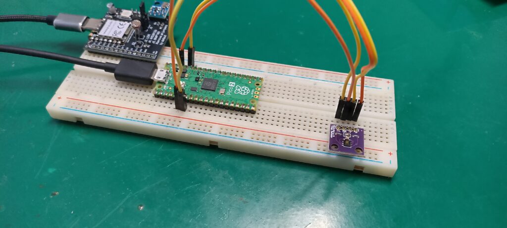
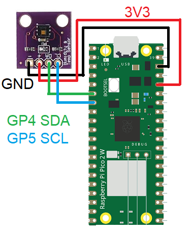
Practical and simple HDC1080 datasheet states that is needs i2c communication in order to supply its data. So besides SDA and SCL, we also need +3.3V and GND, supplied by the Pi Pico 2 itself. Supply voltage to the RP2350 itself comes via USB C connection, which also brings data to the board. Look in the image below for the schematic diagram for this post’s experiment.
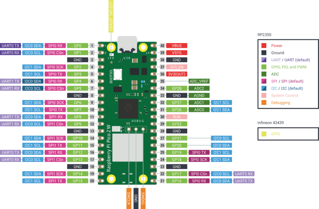
Raspberry Pi Pico 2’s i2c port can be positioned in a variety of pins, as for example i2c0 can go in pins 1-2, 4-5, 8-9, 16-17, and so on. The “official” and “original” pins are 4 and 5, to be compatible with Arduino (which uses pins A4 and A5). See below the complete Pi Pico 2 pinout diagram.
Configuring Thonny IDE
Go to Thonny IDE’s website and download your preferred version (actually the version that fits your operating system). Mine is Windows; follow the instructions on screen to install it (just like any other software installation). When you open the IDE there is going to be a menu on the top part of the screen, containing “File”, “Edit”, “View”, “Run”, “Tools” and “Help”.
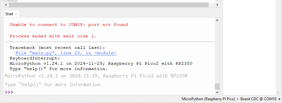
Go to “Tools > Options…” and at this time connect your Raspberry Pi Pico 2 board to the computer via a USB cable. Go to “Interpreter” submenu and at the drop-down menu select “Micropython (Raspberry Pi Pico)”. Then on “Port or WebRPL” drop-down menu select the single (only) COM port that shows. Click “OK” and observe the bottom part of the screen, it has to look something like the image below.
It features microPython version, board name and “>>>” waiting for you to type something. This means the board was recognized by Thonny IDE as running microPython, and is ready to go.
Coding for HDC1080 temperature sensor
Code for our practical and simple HDC1080 sensor is not mine, I actually found it on Github at this link. You will have to create two “.py” files in order for this example to work, one is the HDC1080 code at “hdc1080.py”. The other is our main file containing the function’s usage and screen printing (“main.py”). Both will have to be saved on the Pi itself, not in your computer.
First copy the code below:
# SPDX-FileCopyrightText: 2024 Mike Causer <https://github.com/mcauser>
# SPDX-License-Identifier: MIT
"""
MicroPython HDC1080 Temperature & Humidity Sensor
https://github.com/mcauser/micropython-hdc1080
"""
__version__ = "1.0.1"
from micropython import const
from time import sleep_ms
# registers
_TEMPERATURE = const(0x00)
_HUMIDITY = const(0x01)
_CONFIG = const(0x02)
_SERIAL_ID0 = const(0xFB)
_SERIAL_ID1 = const(0xFC)
_SERIAL_ID2 = const(0xFD)
_MANUFACTURER_ID = const(0xFE)
_DEVICE_ID = const(0xFF)
class HDC1080:
def __init__(self, i2c):
self._i2c = i2c
self._address = 0x40 # fixed I2C address
self._buf1 = bytearray(1)
self._buf2 = bytearray(2)
self._config = 0x10
def _read16(self, reg):
self._buf1[0] = reg
self._i2c.writeto(self._address, self._buf1)
sleep_ms(20)
self._i2c.readfrom_into(self._address, self._buf2)
return (self._buf2[0] << 8) | self._buf2[1]
def _write_config(self):
self._buf2[0] = _CONFIG
self._buf2[1] = self._config
self._i2c.writeto(self._address, self._buf2)
def _read_config(self):
# shift out the first 8 reserved bits
self._config = self._read16(_CONFIG) >> 8
def check(self):
if self._i2c.scan().count(self._address) == 0:
raise OSError(f"HDC1080 not found at I2C address {self._address:#x}")
return True
def config(
self, config=None, humid_res=None, temp_res=None, mode=None, heater=None
):
if config is not None:
self._config = config
self._write_config()
else:
self._read_config()
if humid_res is not None:
# 00 = 14-bit, 01 = 11-bit, 10 = 8-bit
if humid_res == 8:
self._config |= 2
self._config &= ~1
elif humid_res == 11:
self._config &= ~2
self._config |= 1
elif humid_res == 14:
self._config &= ~3
else:
raise ValueError("humid_res must be 8, 11 or 14")
if temp_res is not None:
# 0 = 14-bit, 1 = 11-bit
if temp_res == 11:
self._config |= 4
elif temp_res == 14:
self._config &= ~4
else:
raise ValueError("temp_res must be 11 or 14")
if mode is not None:
# mode 0 = temp or humid acquired
# mode 1 = temp and humid acquired in sequence, temp first
self._config &= ~16
self._config |= (mode & 1) << 4
if heater is not None:
self._config &= ~32
self._config |= (heater & 1) << 5
self._write_config()
def reset(self):
self._config = 128
self._write_config()
# sw reset bit self clears
self._read_config()
def battery_status(self):
# returns 0 if Vcc > 2.8V
# returns 1 if Vcc < 2.8V
self._read_config()
return (self._config >> 3) & 1
def temperature(self):
# temperature in celsius
return (self._read16(_TEMPERATURE) / 65536) * 165 - 40
def humidity(self):
# relative humidity percentage
return (self._read16(_HUMIDITY) / 65536) * 100
def serial_number(self):
# unique per device
return (
(self._read16(_SERIAL_ID0) << 24)
| (self._read16(_SERIAL_ID1) << 8)
| (self._read16(_SERIAL_ID2) >> 8)
)
def manufacturer_id(self):
# fixed 21577 == 0x5449 == b'\x54\x49' == b'TI'
return self._read16(_MANUFACTURER_ID)
def device_id(self):
# fixed 4176 == 0x1050 == b'\x10\x50' == b'\x10P'
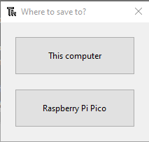
return self._read16(_DEVICE_ID)Paste it on the Thonny IDE and go “File > Save As..”, then pick “Raspberry Pi Pico” at the menu below. Name it “hdc1080.py”.
Go “File > New” and copy/paste the code below, our main code:
# SPDX-FileCopyrightText: 2024 Mike Causer <https://github.com/mcauser>
# SPDX-License-Identifier: MIT
"""
MicroPython HDC1080 Basic example
Prints the temperature and humidity every 500ms
"""
from machine import I2C
from hdc1080 import HDC1080
i2c = I2C(0)
hdc = HDC1080(i2c)
from time import sleep_ms
hdc.config(humid_res=14, temp_res=14, mode=0, heater=0)
if hdc.check():
print(f"Found HDC1080 with serial number {hdc.serial_number()}")
while True:
print(f"{hdc.temperature()} C, {hdc.humidity()} RH")
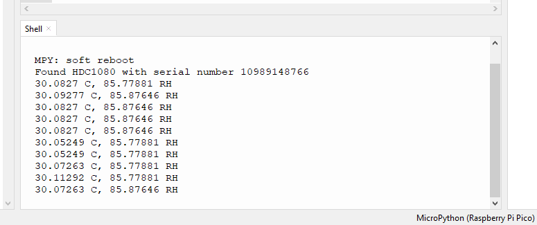
sleep_ms(1000)Then go “File > Save As”, pick “Raspberry Pi Pico” and name it “main.py”. Now Click the green arrow at the top of the screen (“Run current script”) or press “F5”. You will start seeing information being printed at the bottom part of the screen, like in the image below.
To finish it up
Fist you will see the HDC1080 board serial number, then temperature in degrees Celsius and humidity in %RH will show on the screen every 1000ms (1 second). One thing that I noticed is that every time you remove the board’s connection (USB) and reconnects it, you have to do a small process.
This process involves going to “Tools > Options” and re-selecting the COM port. Also you have to click the green arrow at the top of the screen (run code, “F5”) again every time. I guesse this is part of the usage of a “newish” technology that is easy at one side and more complex at the other. Below is a video of me showing how this sensor works with the RP2350.


Pingback: Thermocouple with MAX6675 in microPython - FritzenLab electronics
Pingback: DHT11 temperature sensor with microPython - FritzenLab electronics
Pingback: 433MHz radio with Arduino and ESP32 - FritzenLab electronics
Pingback: Master the round display GC9A01 with microPython - FritzenLab electronics