In this article we will learn how to contro the Easy to use ST7735 display with Raspberry Pi RP2040 Zero and Arduino code. We will read a LM35 temperature sensor and show temperature in the display.
The reason we will use a RP2040 instead of the newer RP2350 is because I just bought a couple fo RP2040 Zero from Waveshare, a very tiny module that actually fits in a corner of the breadboard. This specific board features dual core ARM Cortex M0+ and 20 GPIOs broken out on the edges of the board. Nine (9) more GPIOs are available by soldering wires to “test points” on the board.
ST7735 is a TFT LCD controller/driver whose datasheet is here, for reference. This specific display I have communicates via SPI and has a resolution of 128×160 pixels in 262k (262,000) colors. Its size is 1.8″ (inches) with eight (8) pins for supply and communication.
I am using LM35 as the temperature sensor for this build, since it is a simple and straightforward one to use. It “spits” 10mV per degree Celsius, so for example when the temperature is 22ºC it will present 220mV (0,22V). I will also present an “up time” counter on screen, incrementing every one second without stop.
Hardware and connections
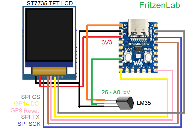
This build has three main components: a 1.8″ easy to use ST7735 TFT LCD, one LM35 temperature sensor and the RP2040 Zero microcontroller. Important to say that you don’t need a RP2040, basically any Arduino-compatible microcontroller will do the job for us. This link has the pinout for the RP2040 Zero and this one for the ST7735. Everything is reproduced in the image below for clarity.
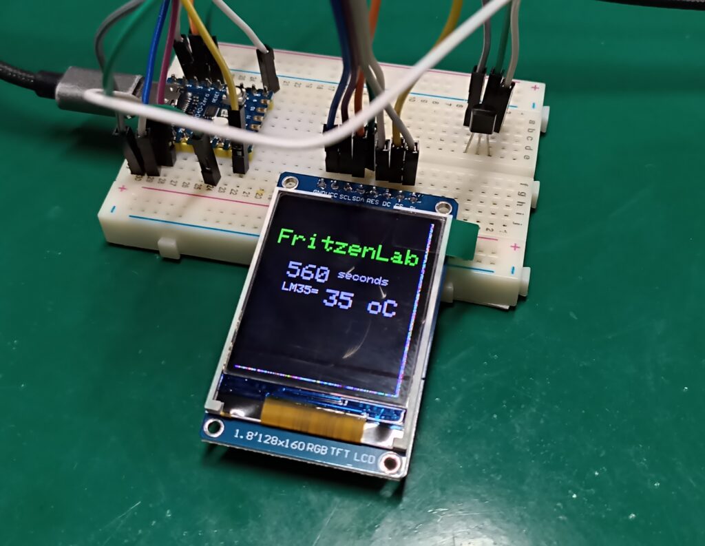
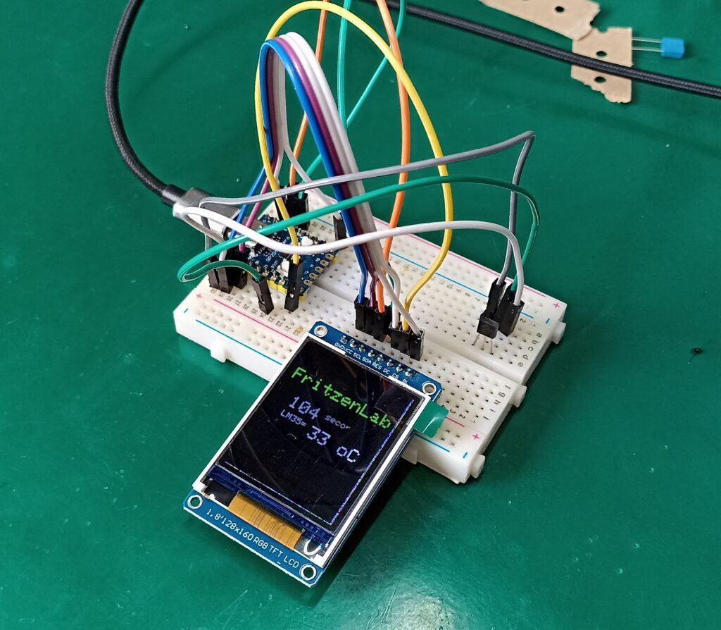
I bought the 1.8″ ST7735 display from Aliexpress using this link (my affiliate link). It has a decent screen size, specially when compared to those 16×2 LCD displays, which are monochromatic. This one has full RGB colors and a quick update rate. See below for a picture of the assembly in my bench.
Code/firmware
There is a neat little library made by Adafruit for this display. ST7735 can be controlled by it, including drawing graphics like lines, triangles, rectangles, etc. One can also change font size and color for the text. To install it in your Arduino IDE, go to “Sketch > Include library > Manage Libraries” and type “ST7735”; install the one from Adafruit.
Let’s then talk about some limitations of (either) the display or the library. As far as I can tell there is now way to reproduce videos or GIFs or any animated things on this display. One can show bitmap images on it by storing it on an SDcard. My module doesn’t have it so I won’t show you how to do this at this time.
Another serious limitation of this library (or display) is that there is no “clear” function for parts of the display, so if you want to show new text of top of the old one you can do one of two things:
- Clear the entire display using “tft.fillScreen(ST77XX_BLACK);” which fills the screen with a color of your choice, or
- Draw a form (for example a rectangle) with a solid color that is the same as the background one.
None of the forms are ideal, both make the display “blink” in an ugly and noticeable way. Despite not being ideal, I decided to make and example implementing the rectangle drawing technique. I wrote a code that reads temperature from an analog LM35 sensor (datasheet here) and updates the reading and the screen each 20ms (0.02 seconds). Even at 50Hz update rate the display still “blinks” a little as you are going to see in the video below.
I also put two more things on display: the word “FritzenLab” in green color and a counter for every second that has passed, in white color. Look at the code below. Also please notice that the SPI and other function’s pinouts may vary from board to board, those pins work for my RP2040 Zero from Waveshare.
#include <Adafruit_GFX.h>    // Core graphics library
#include <Adafruit_ST7735.h> // Hardware-specific library for ST7735
#include <Adafruit_ST7789.h> // Hardware-specific library for ST7789
#include <SPI.h>

// For the breakout board, you can use any 2 or 3 pins.
// These pins will also work for the 1.8" TFT shield.
#define TFT_CS        1
#define TFT_RST        8 // Or set to -1 and connect to Arduino RESET pin
#define TFT_DC         14


// OPTION 1 (recommended) is to use the HARDWARE SPI pins, which are unique
// to each board and not reassignable. For Arduino Uno: MOSI = pin 11 and
// SCLK = pin 13. This is the fastest mode of operation and is required if
// using the breakout board's microSD card.

// For 1.44" and 1.8" TFT with ST7735 use:
Adafruit_ST7735 tft = Adafruit_ST7735(TFT_CS, TFT_DC, TFT_RST);


void setup(void) {
  Serial.begin(9600);
  Serial.print(F("Hello! ST77xx TFT Test"));
  analogReadResolution(12);

  // Use this initializer if using a 1.8" TFT screen:
  tft.initR(INITR_BLACKTAB);      // Init ST7735S chip, black tab

  Serial.println(F("Initialized"));

  uint16_t time = millis();
  tft.fillScreen(ST77XX_BLACK);


  // large block of text
  tft.setTextSize(2);
  tft.fillScreen(ST77XX_BLACK);
  tft.setCursor(5, 30);
  tft.setTextColor(ST77XX_GREEN);
  tft.println("FritzenLab");
  delay(1000);
  tft.setCursor(5, 60);

}

void loop() {

  int temperature= analogRead(A0) * 3.3 / 4095 * 100; // Equation for LM35 to Celsius degrees
  tft.setTextSize(2);
  tft.setCursor(20, 60);
  tft.setTextColor(ST77XX_WHITE);
  //tft.println("     ");
  //tft.setTextColor(39321);
  tft.print(millis() / 1000);
  tft.setTextSize(1);
  tft.println(" seconds");
  tft.setCursor(20, 80);
  tft.print("LM35= ");
  tft.setTextSize(2);
  tft.print(temperature);
  tft.println(" oC");
  delay(5);
  testdrawrects(ST77XX_BLACK);
  delay(5);
}

void testdrawrects(uint16_t color) {

  tft.fillRect(5, 50, 100, 60, color);
  tft.drawRect(5, 50, 100, 60, color);

}
That code is also in my Github using this link. Notice the equation to obtain temperature from the LM35 readings:
int temperature= analogRead(A0) * 3.3 / 4095 * 100; // Equation for LM35 to Celsius degreesFirst I have to transform the 0..4095 integers into volts, so I do “3.3 / 4095”. Then I multiply all by 100 since this is the number of steps of the 10mV/ºC resolution sensor into a single volt (1 / 0.01). I have talked about LM35 before in this post.
Testing
I made a video showing you the entire process: the display, the RP2040, LM35, SPI connections and code on the Arduino IDE. I hope you enjoy and understand it. Also please use my affiliate Aliexpress link to buy this easy to use ST7735 display.


