In this post we are going to create analog voltage with PCF8591, a chip from NXP with 8bit analog to digital (ADC) and digital to analog (DAC) converters. We are using ESP32-C6 for this task, but you can surely use an Arduino UNO or similar, no problem.
As stated we are focusing in the DAC part (digital to analog), so the ADC part (analog to digital) will be seen in another article. Our chip of interest, PCF8591 (datasheet here) is capable of both. I am using an ESP32-C6 because it is what I have in hands, also it is assembled into a PCB I made myself, see here.
I bought PCF8591 from Aliexpress (link here) assembled in a small PCB, featuring a couple of interesting things. It features three analog components: a LDR, a potentiometer and a NTC, each connected to a different analog input. Our module PCF8591 has four analog inputs.
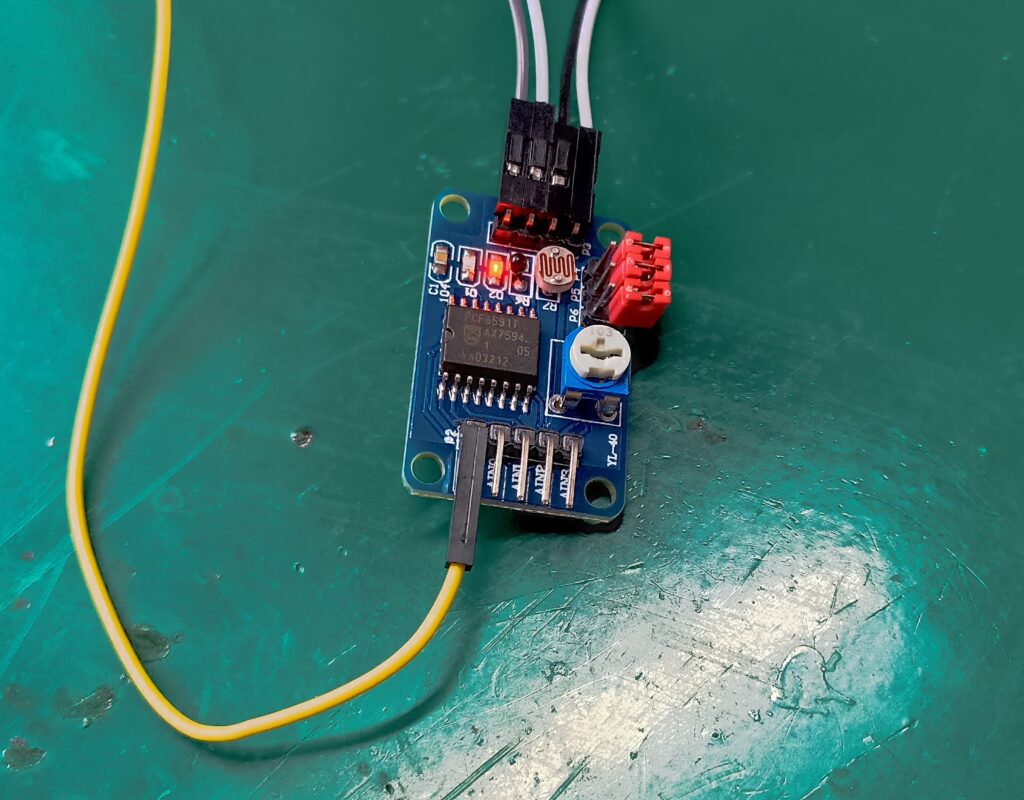
There are four red jumpers on the board, we will open all of them. This is to disconnect the analog sensors from the board. You can see a yellow wire in the picture above, which is the DAC output of interest for us. The wires on the top are i2c and power supply.
Hardware and schematics
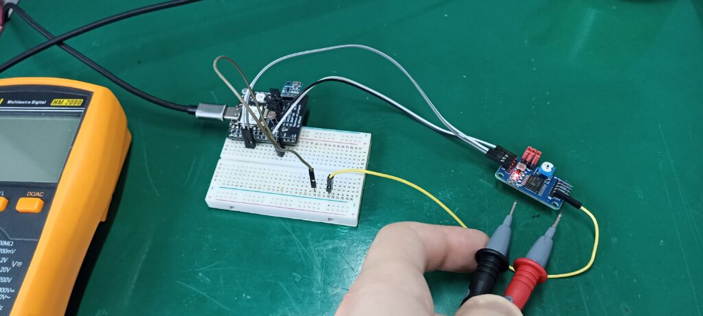
Materials necessary for our experiment with PFC8591 DAC are the module itself, an ESP32 or Arduino, a breadboard and one multimeter. We are using the multimeter to measure voltage generated by the PCF8591, so remember to place it in DC voltage measurement (up to 3.3V). Complete schematics and assembly on the bench is seen below.
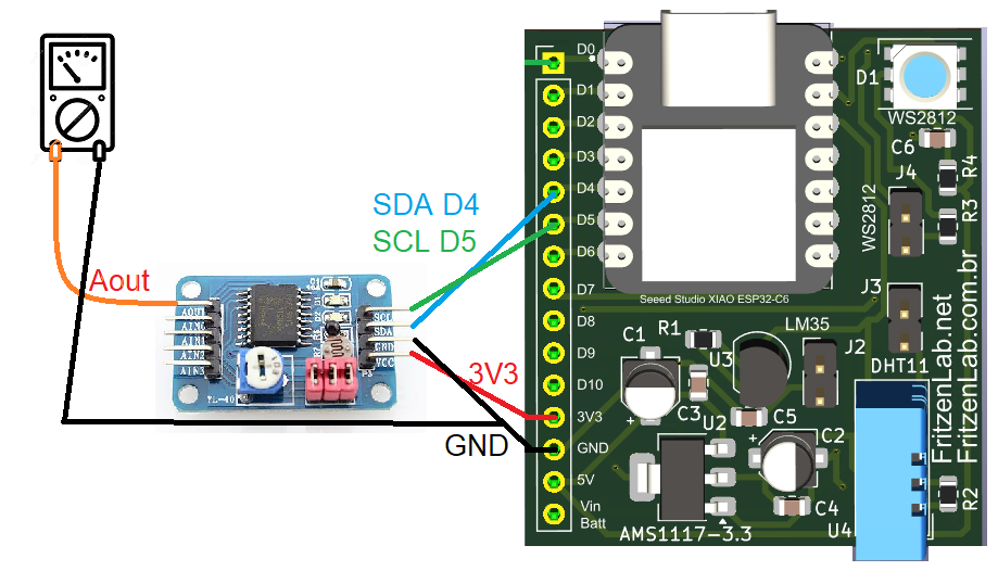
Just to be on the safe side, note that I am using D4 and D5 as SDA and SCL (for i2c); on an Arduino UNO for example such pins will be A4 and A5, so make sure you know your board.
Code and programming
After assembling the circuit on the bench, we are going to give some attention to the programming side of the experiment. We are using the Arduino IDE software (I use the 2.x.x version) for programming in Arduino language. I suggest you make sure your board can be programmed via the Arduino IDE, by uploading a LED blink example to it.
PCF8591 is an i2c device, so it needs a library in order to answer to our commands. I end up picking the Adafuit one, which is simple and straightforward enough. To install it in your Arduino IDE, got to “Sketch > Include library > Manage libraries” and type “PCF8591”; install the one that says “Adafruit” as author.
There is a complete example of the workings of the library, in “File > Examples > Adafruit PCF8591 > PCF8591”. I used this example to create the sketch we are going to use in the blog post (so it is not the raw example). What I implemented was to read the serial monitor for values between 0.00 and 3.30, values you type in the Arduino IDE.
These values represent a voltage you want to see in the analog output. Then every 500ms (0.5 seconds) I get such values and map them to 0-255, which represents 8bit (which is the resolution of the analog output). You can see the complete code below. Note that I don’t use any delay(), so the code in non-blocking, which means you can put whatever code you want on top of mine that it will jut work.
#include <Adafruit_PCF8591.h>
// Make sure that this is set to the value in volts of VCC
#define ADC_REFERENCE_VOLTAGE 3.3
Adafruit_PCF8591 pcf = Adafruit_PCF8591();

int SerialValue;
long oldtime;
long oldtime2;
int valueToWrite;


void setup() {
  Serial.begin(115200);
  while (!Serial)
    delay(10);

  pcf.begin();
  pcf.enableDAC(true);
  Serial.println("Type a value between 0.00 and 3.30 (a voltage)");
}

uint8_t dac_counter = 0;

void loop() {


  if (Serial.available() > 0) {
    // read the incoming byte:
    SerialValue = (Serial.readString().toFloat())*100;
    valueToWrite= map(SerialValue, 0, 330, 0, 255);

  }

  if(millis() - oldtime2 > 500){
    oldtime2= millis();
    pcf.analogWrite(valueToWrite);
  }
}
A couple of important things: you have to set which voltage you are supplying the PCF8591 with, in the line below:
#define ADC_REFERENCE_VOLTAGE 3.3Also the line below is the hearth of the program. Command “Serial.readString()” gets the typed in value as string, gets converted to float back again. Then it is multiplied by 100, so that for example 3.30 becomes 330 and 1.25 becomes 125, values usable to then map to 0-255.
SerialValue = (Serial.readString().toFloat())*100;Create analog voltage
I made a video illustrating how this experiment works. Basically you type a value in the serial monitor of the Arduino IDE and the value gets written to the PCF8591 output. This is then seen with a multimeter to confirm what we typed in.
Also remember, if you want to buy the PCF8591 from this experiment, go to my Aliexpress affiliate link.


Pingback: Create analog voltage with MCP4725 - FritzenLab electronics