We are going to study a way How to Dominate the creation analog voltages with MCP4725 and ESP32-C3, using Arduino code and Arduino IDE. MCP4725 is a 12bit DAC (digital to analog converter) chip in a SOT23-6 (6 pins) configuration. Made by Microchip and with the datasheet available here, this little chip works from 2.7 to 5.5V and communicates via i2c.
We are supplying it with 3.3V because we are using an ESP32-C3 mini as the controller. As stated the communication between MCP4725 and ESP32-C3 is via i2c, using only two wires (SDA and SCL).
Hardware
I decided to write this piece using an ESP32-C3, but nothing stops you from using whatever board you have in hands. After all this is only i2c, something any Arduino can do; Code from this write up will compile just fine for you. You can see the schematic diagram below, multimeter included (to measure voltage).
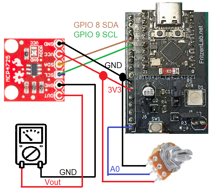
Pretty simple circuit, GPIO 8 of the ESP32-C3 is SDA and GPIO 9 is SCL. Supply 3.3V and GND and connect a multimeter (in voltage mode) to OUT and GND, besides a 10k Ohm potentiometer for voltage reference. Potentiometer is used to generate a voltage referente, so that our analog output will follow it.
Code and testing
We are using Arduino IDE and Arduino code for this example. For devices like the MCP4725, which works via i2c, it is interesting to have a library take care of things for us. I have installed a library called “MCP4725” from Rob Tillaart, going “Sketch > Include library > Manage libraries” and type “MCP4725”. Install the Rob Tillaart one.
I then wrote code myself, based on an example available in the IDE. Go to “File > Examples > MCP4725 > MCP4725_test”. My modified version of the code is seen below.
//   Created by Clovis Fritzen, FritzenLab.net
// Based on work from:
//    FILE: mcp4725_minimal.ino
//  AUTHOR: Rob Tillaart
// PURPOSE: Minimal sketch MCP4725 (#29)
//     URL: https://github.com/RobTillaart/MCP4725


#include "Wire.h"
#include "MCP4725.h"

MCP4725 MCP(0x60);

long oldtime;
int rawAnalog;
int i= 0;

void setup()
{
  Serial.begin(115200);

  Wire.begin();
  MCP.begin();

  //analogReadResolution(12);
}
void loop()
{
  if(millis() - oldtime > 100){
    oldtime= millis();
    rawAnalog= analogRead(A0);
    MCP.setValue(rawAnalog);

    i++;
    if(i == 10){
      Serial.println(rawAnalog);
      i=0;
    }
  }
}
Everything happens every 100ms (milisseconds), the rest of the time the microcontroller is free to do whatever you ask it to do. There is no delay(), so no blocking code. I basically read analog input A0 (potentiometer) and store it in “rawAnalog”, then do “MCP.setValue(rawAnalog) to write the value to MCP4725.
Since this is done every 100ms, looks almost continuous to the human eye (specially in the multimeter). I also print “rawAnalog” value to the Serial monitor every 1000ms (10x 100ms).
Final words
This is how to Dominate the creation analog voltages with ESP32 and Arduino IDE. I made a video to become more clear how the system works, enjoy. Also before you go, want to see me testing another DAC? click here. Also if you want to buy the MCP4725 use my affiliate link.


