LED display made easy. This article will teach you how to control a 7 segment LED display (buy here) and ESP32-C6 – common anode. We have seen such 7 segment displays before, here, in the common cathode configuration. Now we are controlling a common anode one.
Common anode means that the “positive” or 3.3V/5V pin of this display is the common one. Every other pin needs to be put to 0V/GND in order for the segment to light up. See the image below for details (the one on the right).
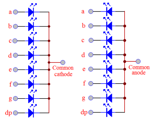
Controlling such display is easy enough, all you need to do is light the corresponding segment (A..G or DP) at the right time. There is no need for multiplexing, but you need eight pins available from your microcontroller (that is a downside). For example to make number one (1) you need segments B and C to light up.
One other source of information you can follow for display controls is this one.
Hardware
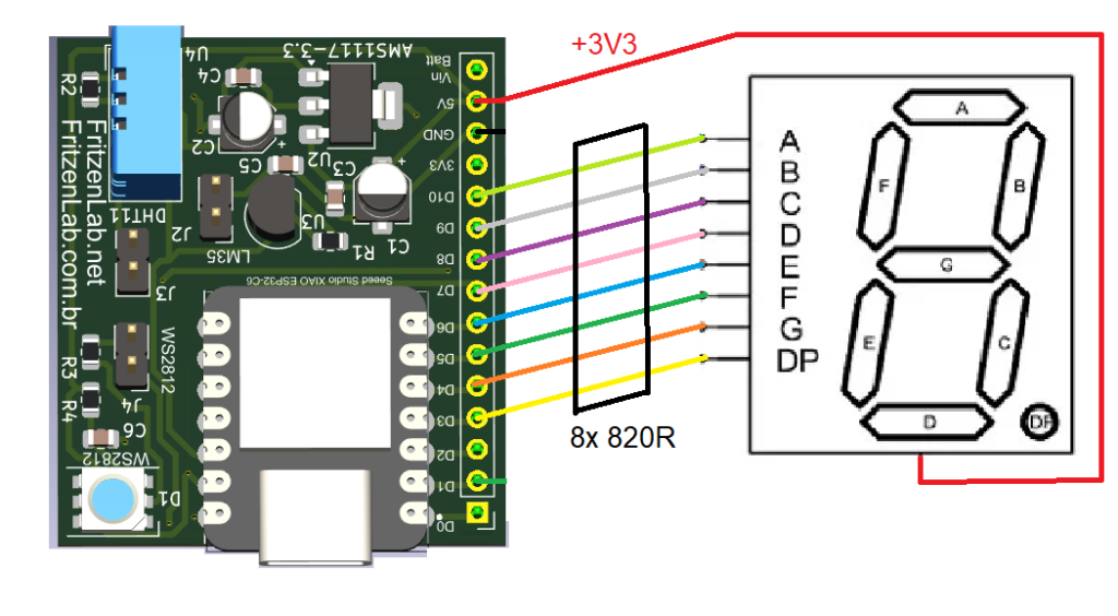
We are using a Xiao ESP32-C6 (from SeeedStudio) for this experiment, but it should work with literally any Arduino. This is due to the fact that we are only using common Arduino functions, like digitalWrite() and millis(). There is also the need for one resistor for each segment/LED, I am using 8x 820 Ohm but you can go down to 220 Ohm each if you want.
Firmware
As stated before, we are using Arduino code with Arduino IDE for programming and controlling this display. If you are going to use any board except the “common ones”, you need to install support for it in the Arduino IDE (as seen here). I decided to create a sketch that counts from 0 to 9 and back again, incrementing the counter every 500ms (half a second).
One of the “good problems” you have with a 7 segments LED display is how to convert an integer (a number) into each segment to light up. There is no mathematics or physics ready to be used, you have to manuall say that (for example) number 8 light every single segment.
What I did was I created a function called “displayControl(integer-here) that takes a number (in “integer-here”) and does a bunch of IF clauses. If the number that came was “0” does this, if it was “5” does that and so on. Then I do digitalWrite() in each pin with the corresponding “0” or “1” that was decided above.
Look at the code below, LED display made easy. Notice that it is non-blocking, means it uses no delay() and you can use it side by side with any other code. What I do is I keep track of time and enter the IF statement every 500ms; the rest of the time Arduino is free to execute any other code.
long oldtime= 0;
int i= 0;
void setup() {
// put your setup code here, to run once:
pinMode(D3, OUTPUT);
pinMode(D4, OUTPUT);
pinMode(D5, OUTPUT);
pinMode(D6, OUTPUT);
pinMode(D7, OUTPUT);
pinMode(D8, OUTPUT);
pinMode(D9, OUTPUT);
pinMode(D10, OUTPUT);
}
void displayControl(int seg){
int segments[8]= {0};
if(seg == 0 || seg > 9){ // DP, g, f, ....
segments[0]=1;
segments[1]= 1;
segments[2]=0;
segments[3]=0;
segments[4]=0;
segments[5]=0;
segments[6]=0;
segments[7]=0;
}else if(seg == 1){ // DP, g, f, ....
segments[0]=1;
segments[1]=1;
segments[2]=1;
segments[3]=1;
segments[4]=1;
segments[5]=0;
segments[6]=0;
segments[7]=1;
}else if (seg == 2){ // DP, g, f, ....
segments[0]=1;
segments[1]=0;
segments[2]=1;
segments[3]=0;
segments[4]=0;
segments[5]=1;
segments[6]=0;
segments[7]=0;
}else if(seg == 3){ // DP, g, f, ....
segments[0]=1;
segments[1]=0;
segments[2]=1;
segments[3]=1;
segments[4]=0;
segments[5]=0;
segments[6]=0;
segments[7]=0;
}else if(seg == 4){ // DP, g, f, ....
segments[0]=1;
segments[1]=0;
segments[2]=0;
segments[3]=1;
segments[4]=1;
segments[5]=0;
segments[6]=0;
segments[7]=1;
}else if(seg == 5){ // DP, g, f, ....
segments[0]=1;
segments[1]=0;
segments[2]=0;
segments[3]=1;
segments[4]=0;
segments[5]=0;
segments[6]=1;
segments[7]=0;
}else if(seg == 6){ // DP, g, f, ....
segments[0]=1;
segments[1]=0;
segments[2]=0;
segments[3]=0;
segments[4]=0;
segments[5]=0;
segments[6]=1;
segments[7]=0;
}else if(seg == 7){ // DP, g, f, ....
segments[0]=1;
segments[1]=1;
segments[2]=1;
segments[3]=1;
segments[4]=1;
segments[5]=0;
segments[6]=0;
segments[7]=0;
}else if(seg == 8){ // DP, g, f, ....
segments[0]=1;
segments[1]=0;
segments[2]= 0;
segments[3]=0;
segments[4]=0;
segments[5]=0;
segments[6]=0;
segments[7]=0;
}else if(seg == 9){ // DP, g, f, ....
segments[0]=1;
segments[1]=0;
segments[2]=0;
segments[3]=1;
segments[4]=1;
segments[5]=0;
segments[6]=0;
segments[7]=0;
}
digitalWrite(D3, segments[0]);
digitalWrite(D4, segments[1]);
digitalWrite(D5, segments[2]);
digitalWrite(D6, segments[3]);
digitalWrite(D7, segments[4]);
digitalWrite(D8, segments[5]);
digitalWrite(D9, segments[6]);
digitalWrite(D10, segments[7]);
}
void loop() {
// put your main code here, to run repeatedly:
if(millis() - oldtime > 500){ // enters the display function every "x" milisseconds
oldtime= millis();
if(i < 10){ // counts from 0 to 9
displayControl(i); //sends an integer between 0 and 9 to the display
i++;
}else{
i= 0;
}
}
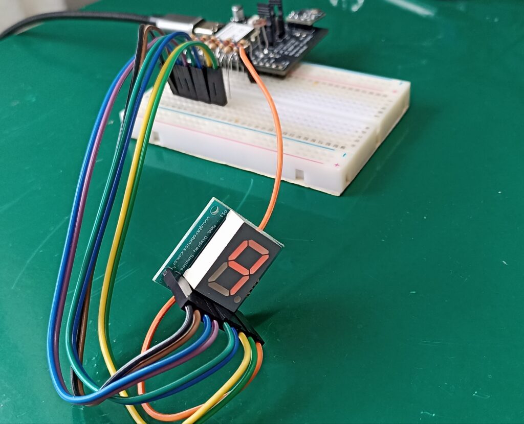
}End result
Code above iterates sequentially between 0 and 9 integers, when it reaches 9 it goes back to 0 in the next iteration. This is a simple application just to demonstrate one can automate such taks in Arduino. See the video and feel free to comment down below or on Youtube.
Want to get to know more about displays? check this e-paper article I made.


