Today we are going to be using PIC12F675 and MPLAB X to blink an LED, using Timer0 interrupts instead of the delay() function. Compiler I am using is the XC8 installed along MPLAB X 6.20, programmer is the (now retired, 2024?) PICkit3. This is part of a bigger project of mine, where I use the PIC12F675 to create an egg/pomodoro timer (15/30/45/60 minutes) that emits light and sound once the time is reached.
Idea is to teach you the complete step-by-step of how to implement a timer interrupt into PIC12F675 (Timer0), while using such interruption to blink an LED in a known interval. We are configuring all necessary registers, whose values I will show you bit by bit.
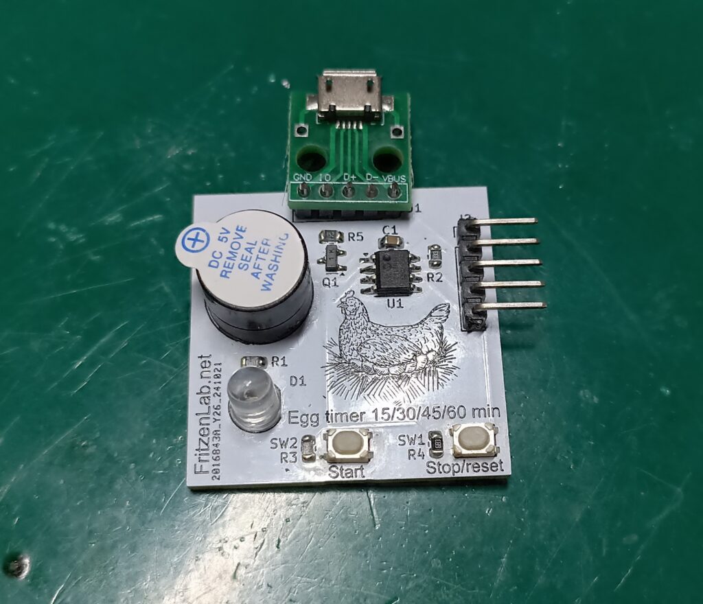
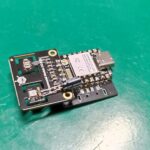
The circuit board I am going to be using is in the picture below, as stated it is a pomodoro/egg timer containing two push buttons, one LED and a buzzer. It is supplied via a micro USB connector and features a 5-pin programming connector.
Schematic diagram
We only need two components besides the PIC12F675 itself: one 1k resistor and one LED (any color). This is due to the fact that we are using PIC’s internal oscillator as clock, and no pin as master clear. So all we need is VCC (5V), GND and the LED + resistor on GP5 pin (pin 2). In my case I am getting power from a USB cable, as seen in the picture below.
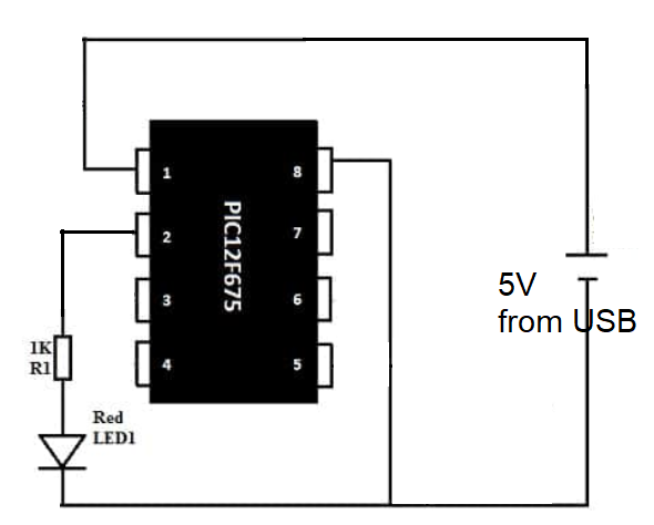
All other components present in my circuit board will not be used in this tutorial, just the LED, resistor and 5V from micro USB.
Programming the PIC microcontroller
I made a series of videos on how to configure the software MPLAB X IDE, watch it here if you feel like doing so. You can see below the way I connected my PIC12F675 to the PICkit3 programmer, five wires are required: +5V (VCC), GND, master clear (MCLR), data (PGD) and clock (PGC).
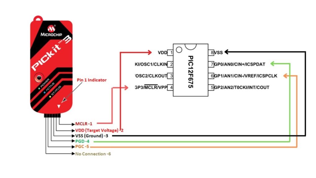
By default the PICkit3 programmer does not supply power to the PIC being programmed, so you would have to supply 5V externally (otherwise programming fails). But MPLAB X has a configuration (a tick box) where you can make PICkit3 supply such voltage, you can even select which voltage you want.
In my experience with PIC12F675 any voltage below 3.6V won’t work (for programming), so I always select the standard 5V. In order to enable such option, In the MPLAB X software I go to “File > Project properties”.
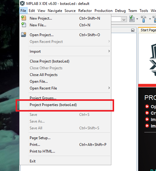
On the left there is a window called “Categories”, click once in “PICkit3”. Then on the top of the screen in the “Option categories” menu select “Power”.
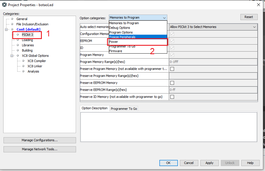
Now tick “Power target circuit from PICkit3” and select 5V (at least for this PIC12F675, yours may require different voltage). Then click “Apply” and “OK”.
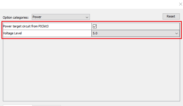
Now next time you click compile and download, our PIC will be powered and programmed by the PICkit3, no external power required.
The code/firmware
To be completely host with you, there are a bunch of ways you can use a timer to blink and LED, PIC12F675 has two timers itself, you can use interrupts or not and so on. I have the XC8 compiler installed in my machine (alonside MPLAB X), so I searched the internet for code that used such compiler.
I actually found a bunch (around 10 I wanna say) different source codes (that did exactly what I wanted), but really none worked first try for me. All required modifications or did not work outright. The one I picked and worked my way onto it is this one, having to mainly modify the interrupt function header to look like this:
void __interrupt() isr() //interruption vector
{

}
Fuses (brown-out, master clear, etc) are like this:
#pragma config FOSC = INTRCIO   // Oscillator Selection bits (INTOSC oscillator: I/O function on GP4/OSC2/CLKOUT pin, I/O function on GP5/OSC1/CLKIN)
#pragma config WDTE = OFF       // Watchdog Timer Enable bit (WDT disabled)
#pragma config PWRTE = ON       // Power-Up Timer Enable bit (PWRT enabled)
#pragma config MCLRE = OFF      // GP3/MCLR pin function select (GP3/MCLR pin function is digital I/O, MCLR internally tied to VDD)
#pragma config BOREN = OFF      // Brown-out Detect Enable bit (BOD disabled)
#pragma config CP = OFF         // Code Protection bit (Program Memory code protection is disabled)
#pragma config CPD = OFF         // Data Code Protection bit (Data memory code protection is enabled)
Now inside the main function at first boot I configure all necessary registers, starting by TRISIO (all pins are outputs):
TRISIO = 0b000000;Option_reg is configured this way (only important bits shown): bit 7 pull-ups disabled, bit 5 Internal instruction cycle clock (CLKOUT), bit 3 Prescaler is assigned to the TIMER0 module, bits 2, 1 and 0 prescaler of 256:
OPTION_REG = 0b10000111;Register INTCON bit 7 Enables all unmasked interrupts, bit 6 Enables all unmasked peripheral interrupts, bit 5 Enables the TMR0 interrupt and the other bits are not important:
INTCON = 0b11100000;Now to define the blinking time we first make the register OSCCAL have the maximum possible frequency, which is coming from the internal oscillator at 4MHz:
OSCCAL = 0b11111111;By the way, PIC12F6275’s datasheet is here if you want to follow along. Since this PIC is running at 4Mhz, its internal useful frequency is 1MHz. This gives us a complete cycle timer of 1 microssecond. Since Timer0 is an 8-bit timer, there are 256 “steps” before it overflows. Also our prescaler is 256, so our timer0 overflow time is 256 * 256us * 1us = 65536 microssenconds, or 65.536 milisseconds.
I then create a variable that increments every time an interruption occurs, up to eight. This is because 65.536ms * 8 = 524.2 milisseconds. So every 524.2ms a LED toggle occurs.
Complete code and tests
Complete code is below, commented for you. Remember that we are using the MPLAB X 6.20 IDE, XC8 compiler and PICkit3 programmer. Besides the LED I also threw a buzzer to make some noise in the same frequency.
/*
 Based on this code: https://microcontroladores-c.blogspot.com/2014/09/timer0-com-pic12f675.html
 */
#include <stdio.h>
#include <stdlib.h>
#include <xc.h>
#define _XTAL_FREQ 4000000

#define LED GP5
#define Buzzer GP2
/////////////////////////////////////////////////////////configuraçôes//////////////////////////////////////////////////
#pragma config FOSC = INTRCIO   // Oscillator Selection bits (INTOSC oscillator: I/O function on GP4/OSC2/CLKOUT pin, I/O function on GP5/OSC1/CLKIN)
#pragma config WDTE = OFF       // Watchdog Timer Enable bit (WDT disabled)
#pragma config PWRTE = ON       // Power-Up Timer Enable bit (PWRT enabled)
#pragma config MCLRE = OFF      // GP3/MCLR pin function select (GP3/MCLR pin function is digital I/O, MCLR internally tied to VDD)
#pragma config BOREN = OFF      // Brown-out Detect Enable bit (BOD disabled)
#pragma config CP = OFF         // Code Protection bit (Program Memory code protection is disabled)
#pragma config CPD = OFF         // Data Code Protection bit (Data memory code protection is enabled)


volatile uint8_t counter= 0;

void __interrupt() isr()//interrupt vector
{
    counter++;
    if(counter == 8){
        counter= 0;
        LED = ~LED;
        Buzzer= ~Buzzer;

    }

    TMR0IF = 0;//  clear timer0 interrupt flag
    TMR0 = 0;// zeroes timer 0 counting, so that it couts from 256 down to 0 again
}


//////////////////////////////////////////////////////Main routine///////////////////////////////////////////////////////////////
void main(void) {
    TRISIO = 0b000000;// all outputs
    CMCON = 7;// disable comparators
    ANSEL = 0;//no analog ports
    WPU = 0X00;// pull ups disabled
    TMR0 = 0;
    OSCCAL = 0b11111111;// internal oscillator to max frequency
    OPTION_REG = 0b10000111;
    INTCON = 0b11100000;


    Buzzer= 1;

    while(1)
    {


    }//infinite loop

}
Leave a Reply