Today I will show you how I made a DIY RGB light box with Arduino, neopixels and battery powered. It is originally intended to be a gift for my daughter, niece and nephew. I firstly had this idea back in 2018, when I made a custom signage for the blog (I was even featured on Hackaday).
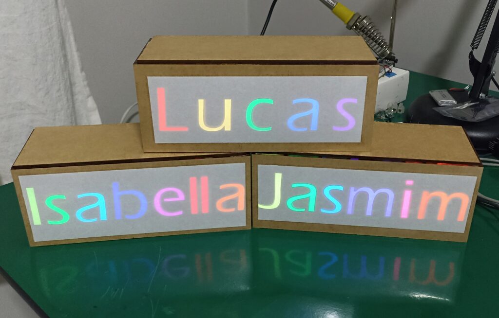
The above image shows the end result, the three boxes all light up and running. Let’s got through the making process for the boxes, I’ll show you everything you need to know to make your own.
Mechanical part
I don’t actually know what type of wood was used to make these boxes, all I know is that it is 3mm wide and was laser cut. It is a common type of wood for crafts, at least here in Brazil. To put the pieces together there was no indents/notches, I had to use wood glue. Initially I was skeptical wether the glue would really hold everything together, but it proved to be strong.
Below you can see details of two of the boxes, with the glue still fresh. I had to have firm hands for this job.
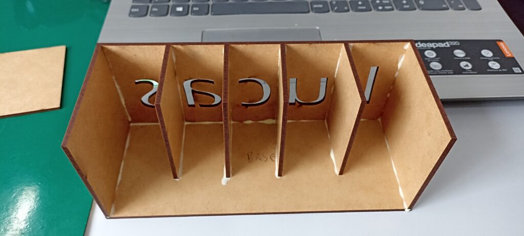
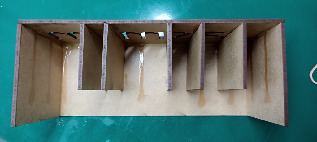
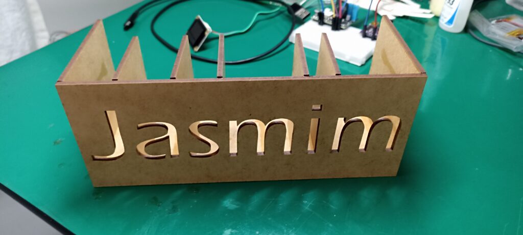
The front panel of the boxes is 20cm wide and 8cm tall, gives me enought space for the lights and electronics. The boxes also are 8cm deep. I don’t have the AutoCAD or SolidWorks files for these, I hired a store to do it for me which did not provide final files.
Front cover
Leaving the letters “as is” would not give the effect I intended, in fact would give no effect at all. In the first version of the box back in 2018, I covered the front face with A4 printer paper, which is barely transparent enough.
The problem with printer paper is that it is not adhesive, so I had to use transparent tape on top of it. For theses boxes I changed my perspective and went looking for a paper that was both white “enough” and also adhesive. I end up finding vinyl adhesive paper, which is used also for inkjet printers, for photographies.
I asked my wife to help me cutting off the white part of the adhesive (the back of it). But just enough to be able to cover the letters with white and leave thick adhesive/vinyl borders. The effect is incredible, as you will see.
Electronics and Arduino
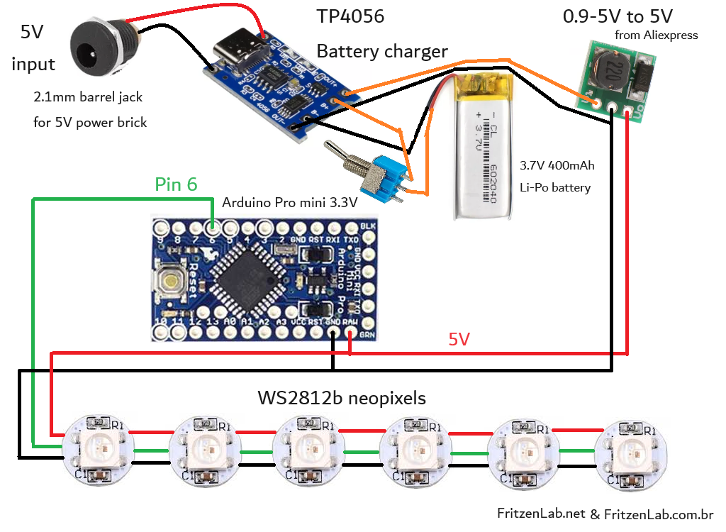
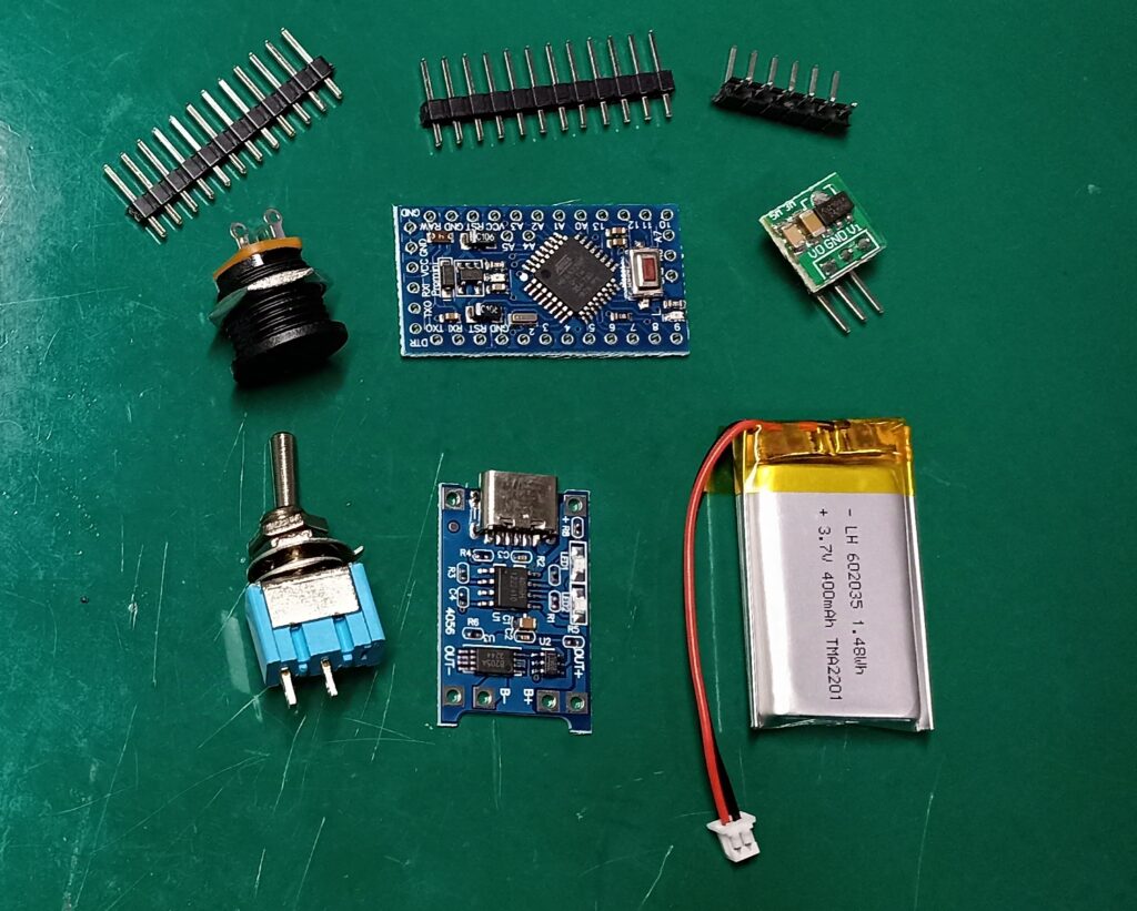
Electronics for the light box is simple yet powerful and somewhat complex. Thanks to Aliexpress one can buy a TP4056 battery charging module ready to use. Also the 5V 600mA boost converter, another ready to use module. Battery is a 3.7V 400mAh Li-Po, the ones of general purpose found on Aliexpress (not necessary to buy the RC hobby ones).
The reason I am using a boost converter from the battery voltage to 5V is because of the WS2812b Neopixels. They don’t work with 3.3V for example (they actually work but don’t show blue for example), so one have to offer them 5V for seamless operation. There is also a power switch midway between the battery and TP4056.
That’s where I decided to interrupt battery power, leaving no part of the circuit energized. Finally the 2.1mm barrel jack receives external power from a 5V power brick (do not use any other voltage, will burn something). Below is the complete schematic with annotations.
Assembly process
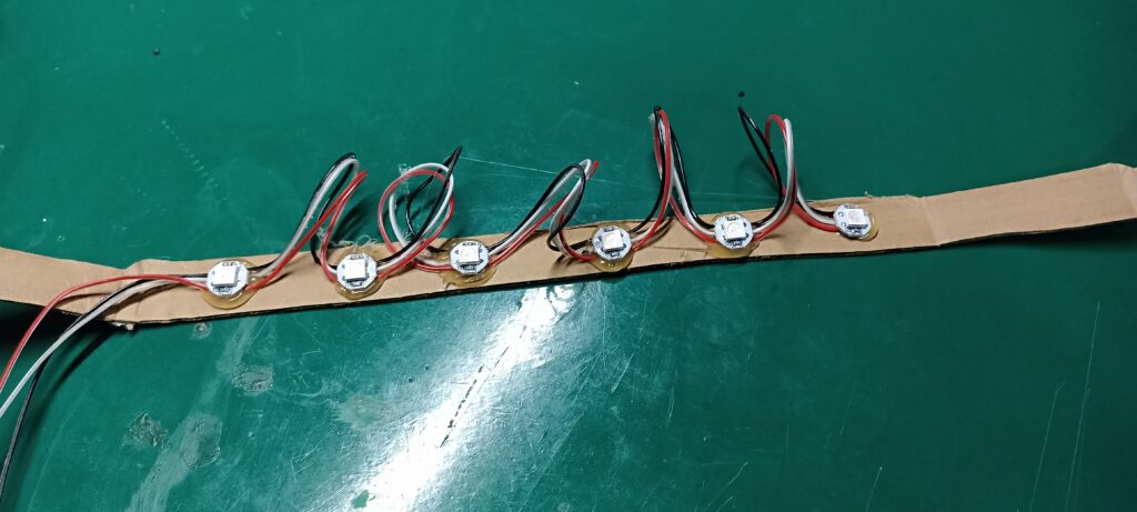
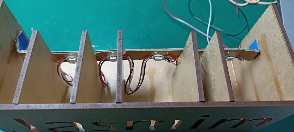
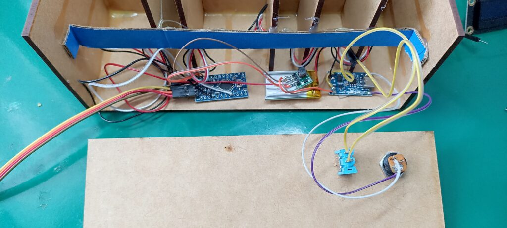
As already stated I put the different box parts together with wood glue. It holds surprisingly well and dries with no color (ok, maybe a slight yellow nuance, not visible due to the wood color). Electronics were all soldered together, no connectors. I decided to go this way because I would never again open up the product, so why spend money on connectors?.
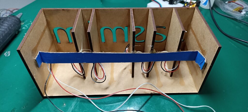
The only exception is the 2.1mm external barrel jack, since the customer has to periodically rechange the device. Look at the pictures below for further details. There is a “bar” that holds all Neopixels together in place, made out of cardboard. Since there are no forces involved this was a cheap solution for LED placement. Used hot gule for this bar and the LEDs.
Arduino code
Programming the Arduino Pro mini is done via an external USB to serial converter (I used a FT232). It is connected to RX, TX and DTR pins, besides GND (no VCC, I supply 5V during programming via the battery). This way you don’t stress the USB to serial converter taking power from it.
I originally intended to write my own code for this project, with the effects I wanted and the timing I wanted. Then during the initial phase of programming I found out about this Arduino sketch. It comes with the “Adafruit Neopixel” library and is called “Strandtest.ino”. You basically define which Arduino pin you want to use and how many LEDs you have, and are ready to go. I am using pin 6 of the Pro Mini and a variable quantity of LEDs (depends on the name displayed).
Complete code is seen below, in all its glory. I made some modifications to the original, as for example increasing the brightness. It went from fifty to one hundred.
// A basic everyday NeoPixel strip test program.

// NEOPIXEL BEST PRACTICES for most reliable operation:
// - Add 1000 uF CAPACITOR between NeoPixel strip's + and - connections.
// - MINIMIZE WIRING LENGTH between microcontroller board and first pixel.
// - NeoPixel strip's DATA-IN should pass through a 300-500 OHM RESISTOR.
// - AVOID connecting NeoPixels on a LIVE CIRCUIT. If you must, ALWAYS
//   connect GROUND (-) first, then +, then data.
// - When using a 3.3V microcontroller with a 5V-powered NeoPixel strip,
//   a LOGIC-LEVEL CONVERTER on the data line is STRONGLY RECOMMENDED.
// (Skipping these may work OK on your workbench but can fail in the field)

#include <Adafruit_NeoPixel.h>
#ifdef __AVR__
 #include <avr/power.h> // Required for 16 MHz Adafruit Trinket
#endif

// Which pin on the Arduino is connected to the NeoPixels?
// On a Trinket or Gemma we suggest changing this to 1:
#define LED_PIN    6

// How many NeoPixels are attached to the Arduino?
#define LED_COUNT 6

// Declare our NeoPixel strip object:
Adafruit_NeoPixel strip(LED_COUNT, LED_PIN, NEO_GRB + NEO_KHZ800);
// Argument 1 = Number of pixels in NeoPixel strip
// Argument 2 = Arduino pin number (most are valid)
// Argument 3 = Pixel type flags, add together as needed:
//   NEO_KHZ800  800 KHz bitstream (most NeoPixel products w/WS2812 LEDs)
//   NEO_KHZ400  400 KHz (classic 'v1' (not v2) FLORA pixels, WS2811 drivers)
//   NEO_GRB     Pixels are wired for GRB bitstream (most NeoPixel products)
//   NEO_RGB     Pixels are wired for RGB bitstream (v1 FLORA pixels, not v2)
//   NEO_RGBW    Pixels are wired for RGBW bitstream (NeoPixel RGBW products)


// setup() function -- runs once at startup --------------------------------

void setup() {
  // These lines are specifically to support the Adafruit Trinket 5V 16 MHz.
  // Any other board, you can remove this part (but no harm leaving it):
#if defined(__AVR_ATtiny85__) && (F_CPU == 16000000)
  clock_prescale_set(clock_div_1);
#endif
  // END of Trinket-specific code.

  strip.begin();           // INITIALIZE NeoPixel strip object (REQUIRED)
  strip.show();            // Turn OFF all pixels ASAP
  strip.setBrightness(100); // Set BRIGHTNESS to about 1/5 (max = 255)
}


// loop() function -- runs repeatedly as long as board is on ---------------

void loop() {
  // Fill along the length of the strip in various colors...
  colorWipe(strip.Color(255,   0,   0), 100); // Red
  colorWipe(strip.Color(  0, 255,   0), 100); // Green
  colorWipe(strip.Color(  0,   0, 255), 100); // Blue

  // Do a theater marquee effect in various colors...
  theaterChase(strip.Color(127, 127, 127), 100); // White, half brightness
  theaterChase(strip.Color(127,   0,   0), 100); // Red, half brightness
  theaterChase(strip.Color(  0,   0, 127), 100); // Blue, half brightness

  rainbow(10);             // Flowing rainbow cycle along the whole strip
  theaterChaseRainbow(50); // Rainbow-enhanced theaterChase variant
}


// Some functions of our own for creating animated effects -----------------

// Fill strip pixels one after another with a color. Strip is NOT cleared
// first; anything there will be covered pixel by pixel. Pass in color
// (as a single 'packed' 32-bit value, which you can get by calling
// strip.Color(red, green, blue) as shown in the loop() function above),
// and a delay time (in milliseconds) between pixels.
void colorWipe(uint32_t color, int wait) {
  for(int i=0; i<strip.numPixels(); i++) { // For each pixel in strip...
    strip.setPixelColor(i, color);         //  Set pixel's color (in RAM)
    strip.show();                          //  Update strip to match
    delay(wait);                           //  Pause for a moment
  }
}

// Theater-marquee-style chasing lights. Pass in a color (32-bit value,
// a la strip.Color(r,g,b) as mentioned above), and a delay time (in ms)
// between frames.
void theaterChase(uint32_t color, int wait) {
  for(int a=0; a<10; a++) {  // Repeat 10 times...
    for(int b=0; b<3; b++) { //  'b' counts from 0 to 2...
      strip.clear();         //   Set all pixels in RAM to 0 (off)
      // 'c' counts up from 'b' to end of strip in steps of 3...
      for(int c=b; c<strip.numPixels(); c += 3) {
        strip.setPixelColor(c, color); // Set pixel 'c' to value 'color'
      }
      strip.show(); // Update strip with new contents
      delay(wait);  // Pause for a moment
    }
  }
}

// Rainbow cycle along whole strip. Pass delay time (in ms) between frames.
void rainbow(int wait) {
  // Hue of first pixel runs 5 complete loops through the color wheel.
  // Color wheel has a range of 65536 but it's OK if we roll over, so
  // just count from 0 to 5*65536. Adding 256 to firstPixelHue each time
  // means we'll make 5*65536/256 = 1280 passes through this loop:
  for(long firstPixelHue = 0; firstPixelHue < 5*65536; firstPixelHue += 256) {
    // strip.rainbow() can take a single argument (first pixel hue) or
    // optionally a few extras: number of rainbow repetitions (default 1),
    // saturation and value (brightness) (both 0-255, similar to the
    // ColorHSV() function, default 255), and a true/false flag for whether
    // to apply gamma correction to provide 'truer' colors (default true).
    strip.rainbow(firstPixelHue);
    // Above line is equivalent to:
    // strip.rainbow(firstPixelHue, 1, 255, 255, true);
    strip.show(); // Update strip with new contents
    delay(wait);  // Pause for a moment
  }
}

// Rainbow-enhanced theater marquee. Pass delay time (in ms) between frames.
void theaterChaseRainbow(int wait) {
  int firstPixelHue = 0;     // First pixel starts at red (hue 0)
  for(int a=0; a<30; a++) {  // Repeat 30 times...
    for(int b=0; b<3; b++) { //  'b' counts from 0 to 2...
      strip.clear();         //   Set all pixels in RAM to 0 (off)
      // 'c' counts up from 'b' to end of strip in increments of 3...
      for(int c=b; c<strip.numPixels(); c += 3) {
        // hue of pixel 'c' is offset by an amount to make one full
        // revolution of the color wheel (range 65536) along the length
        // of the strip (strip.numPixels() steps):
        int      hue   = firstPixelHue + c * 65536L / strip.numPixels();
        uint32_t color = strip.gamma32(strip.ColorHSV(hue)); // hue -> RGB
        strip.setPixelColor(c, color); // Set pixel 'c' to value 'color'
      }
      strip.show();                // Update strip with new contents
      delay(wait);                 // Pause for a moment
      firstPixelHue += 65536 / 90; // One cycle of color wheel over 90 frames
    }
  }
}
Final result
Finally after all the assembly and testing phase, I was able to record a video showing how the three boxes I made work.

Leave a Reply