Let’s implement an electronic dice with Raspberry Pi Pico 2 and Arduino code. A dice is a gaming device whose objective is to present a random number between one and six, every time it is played/thrown.

Our electronic dice will feature the Raspberry Pi Pico 2 as the controller. There will be six 5mm LEDs to represent one increment each. So that if for example the sorted number is five, then five LEDs will light up and so on. We will implement such a logic and circuit that a button will have to be pressed to sort a new number.
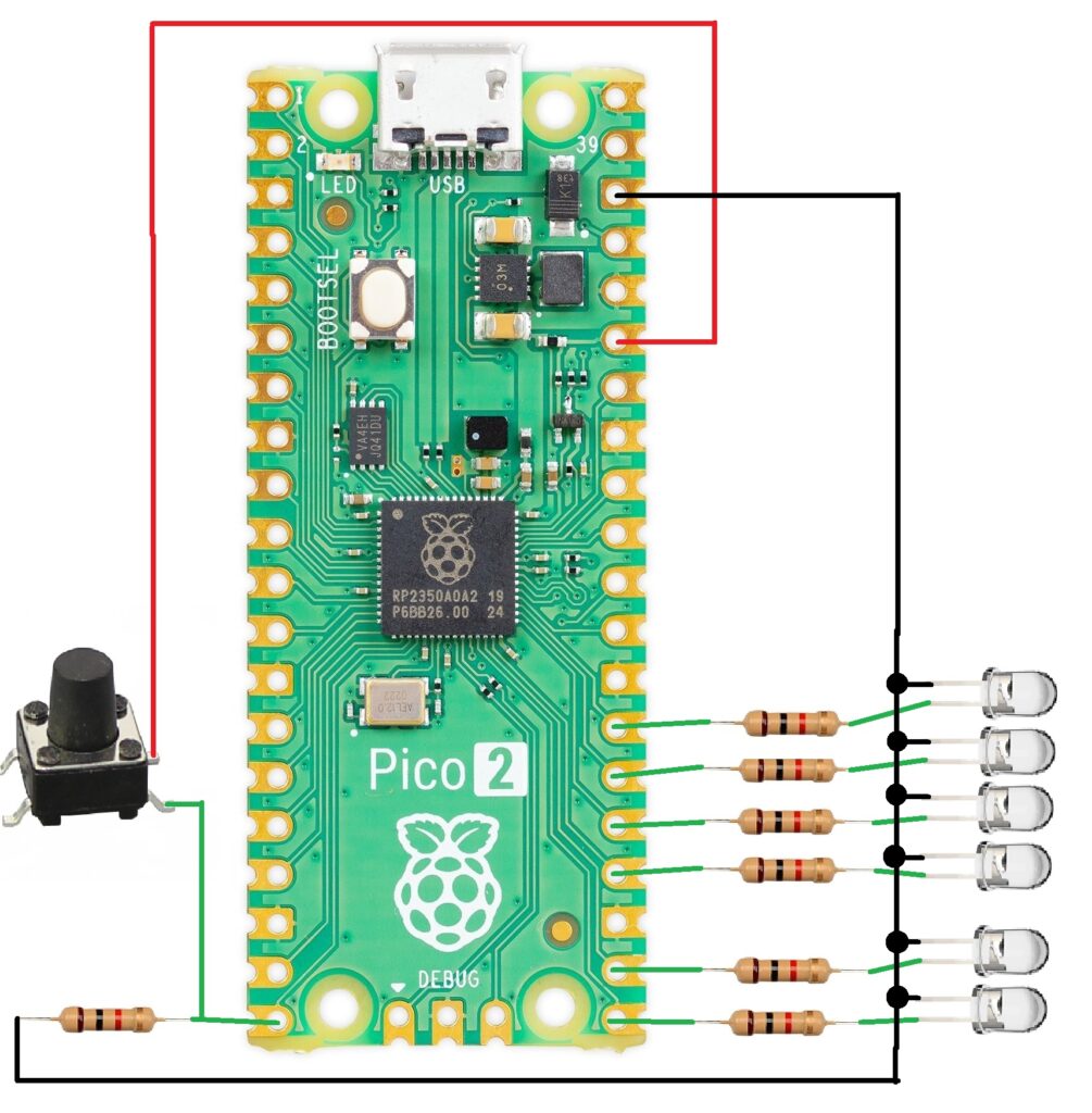
Schematic diagram
We will power supply the Raspberry Pi Pico 2 via USB connection, also used to visualize the sorted number in the Arduino IDE serial monitor. There will be six LEDs, each with a 1k Ohm series resistor. They will be on pins 16, 17, 18, 19, 20, 21. A push-button is put on pin 15 with a 1k Ohm pull-down resistor, to start the sorting process.
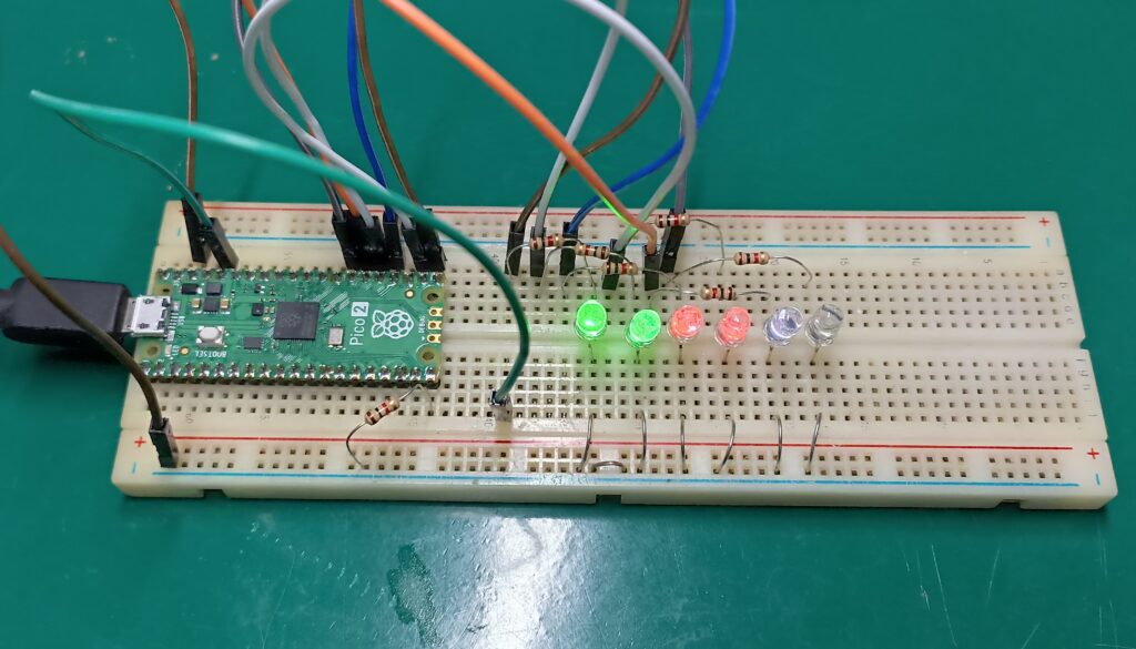
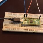
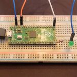
I am assembling this circuit on a breadboard, as you can see below. Since I do not have a push-button at hand right now I will be using a piece of jumper wire. So that when I connect the jumper wire to pin 15 it acts as a button.
The code
I am using the Arduino IDE to program my Pi Pico 2. There is always the option to use microPython as well, but not for this project. The “core” of our code are two functions called random() and randomSeed(), they are responsible for supplying us with the (not so) random numbers.
Regarding wether the generated number is a TRNG (true random number generator) or PRNG (pseudo random number generator), I have found little information. Pi Pico 2’s datasheet briefly cites a TRNG module, but the original Pi Pico does not have it. Also wether or not the Arduino port for the Pi Pico 2 implements such functionality in random(), I don’t know.
All that said I am considering the generated numbers for this project as not completely random. There is a good try to “seed” a random seed upon initializing the Arduino code. It is done by reading the analog input A0, which must be unconnected from anything.
Code is seen below, it relies on three different structures:
- Time control, a structure that executes the code every 300ms and does not use delay()
- Reading a button and deciding wether to enter the code execution or not
- Using rando() to receive a random number between 1 and 6
//Digital pins
const int ledPin1 = 16;
const int ledPin2 = 17;
const int ledPin3 = 18;
const int ledPin4 = 19;
const int ledPin5 = 20;
const int ledPin6 = 21;
const int buttonPin = 15;

int numero = 0;
int delay1= 300000; //in microsseconds
int previousTime= 0;
int contador= 0;

void setup() {
  // set the digital pin as output:
  pinMode(ledPin1, OUTPUT);
  pinMode(ledPin2, OUTPUT);
  pinMode(ledPin3, OUTPUT);
  pinMode(ledPin4, OUTPUT);
  pinMode(ledPin5, OUTPUT);
  pinMode(ledPin6, OUTPUT);
  pinMode(buttonPin, INPUT);

  //Random seed from analog input A0
  randomSeed(analogRead(A0));


  // Start serial communication
  Serial.begin(115200);
}

void loop() {

  if(micros() - previousTime > delay1){
    previousTime= micros();

    if(digitalRead(buttonPin) == HIGH){

     //Random number between one and six
    numero = int(random(1, 7));

    if(numero == 1){
      digitalWrite(ledPin1, HIGH);
      digitalWrite(ledPin2, LOW);
      digitalWrite(ledPin3, LOW);
      digitalWrite(ledPin4, LOW);
      digitalWrite(ledPin5, LOW);
      digitalWrite(ledPin6, LOW);

    }else if(numero == 2){
      digitalWrite(ledPin1, HIGH);
      digitalWrite(ledPin2, HIGH);
      digitalWrite(ledPin3, LOW);
      digitalWrite(ledPin4, LOW);
      digitalWrite(ledPin5, LOW);
      digitalWrite(ledPin6, LOW);

    }else if(numero == 3){
      digitalWrite(ledPin1, HIGH);
      digitalWrite(ledPin2, HIGH);
      digitalWrite(ledPin3, HIGH);
      digitalWrite(ledPin4, LOW);
      digitalWrite(ledPin5, LOW);
      digitalWrite(ledPin6, LOW);

    }else if(numero == 4){
      digitalWrite(ledPin1, HIGH);
      digitalWrite(ledPin2, HIGH);
      digitalWrite(ledPin3, HIGH);
      digitalWrite(ledPin4, HIGH);
      digitalWrite(ledPin5, LOW);
      digitalWrite(ledPin6, LOW);

    }else if(numero == 5){
      digitalWrite(ledPin1, HIGH);
      digitalWrite(ledPin2, HIGH);
      digitalWrite(ledPin3, HIGH);
      digitalWrite(ledPin4, HIGH);
      digitalWrite(ledPin5, HIGH);
      digitalWrite(ledPin6, LOW);
    }else{
      digitalWrite(ledPin1, HIGH);
      digitalWrite(ledPin2, HIGH);
      digitalWrite(ledPin3, HIGH);
      digitalWrite(ledPin4, HIGH);
      digitalWrite(ledPin5, HIGH);
      digitalWrite(ledPin6, HIGH);
    }
  }
  contador++;
  if(contador == 1){
    contador= 0;
    Serial.println(numero);
  }
  }

}
How it works
In the video below you can see the code in action and a complete explanation of the system. As stated you could use any board that runs Arduino code, it will just work.
Final words
There are various ways one could implement an electronic dice, mainly concerning the display type (data presentation). I decided to light up to six LEDs for it. There is also the option of using a microcontroller that gives TRNG, but these are generally more expensive and specialized.
I have previously written about electronic dices wit STM32C0 in here (Portuguese language).


Leave a Reply