In today’s article we will be using a LDR light level sensor. LDR means “light dependent resistor”, which is exactly what this sensor is. It is a resistor whose resistance (between two terminals) depends on the amount of light it receives.
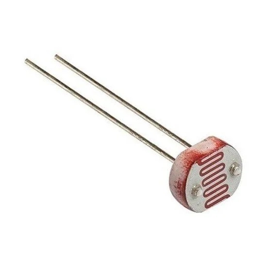
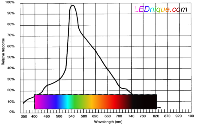
According to this source, its resistance increases with less light and decreases with more light. The spectral response in the image below shows that it is more sensitive to green light than any other color. This is due to its constitution, made of CdS (Cadmium Sulfide).
LDR’s are considered slow devices, with responses taking between 2ms and 50ms. It is much slower than a photodiode or phototransistor for example. This is why you see it mostly being applied to crepuscular detection in public lighting for example. You could of course apply it for robotics in the hobby level, as in Arduino builds.
The test circuit
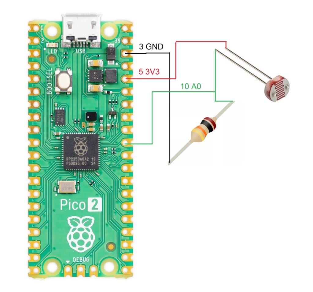
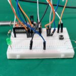
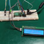
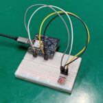
We will implement a simple test circuit, with the LDR in series with a 10k Ohm resistor. It is read by the Raspberry Pi Pico 2 via an analog input, A0. It could really be any other board with an analog input, like the Arduino UNO, ESP32, STM32, PIC family etc.
It is supplied by the 3.3V from the Pi Pico 2 itself, since it intakes a few miliamps only. If you were to use an Arduino UNO you could supply the sensor with 5V no worries. In 3.3V systems like the ESP32 you are better off using 3.3V.
Code for reading the LDR
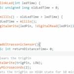
As stated before, interfacing a LDR with a microcontroller is as easy as reading an analog input. It is basically what I do in the code below, every 500ms (half a second) I read the analog input with analogRead(A0). I then print the variable “ldrvalue” to the serial console in the Arduino IDE software.
void setup() {
  // put your setup code here, to run once:
  Serial.begin(115200);
  analogReadResolution(12);
}

void loop() {
  // put your main code here, to run repeatedly:

  int ldrvalue= analogRead(A0);
  Serial.print("LDR raw value= ");
  Serial.println(ldrvalue);
  delay(500);
}
One important feature to remember about the Raspberry Pi Pico 2 is the ability to change the analog input resolution. This is the reason I do analogReadResolution(12), to set the resolution to its maximum (12 bit). it means we can read values between 0 and 3.3V which will translate into integers between 0 and 4095, on the serial monitor.
After you copy and paste the code above in your Arduino IDE, please connect your microcontroller to the computer via USB cable. Then hit the upload button and wait a bit. You can then open the serial monitor of the IDE, doing “Tools > Serial monitor” or Ctrl + Shift + M.
Testing the circuit
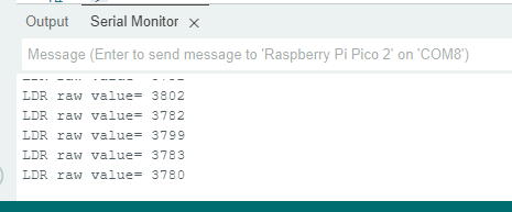
When you open the serial monitor it will start receiving values, just like the image below. By covering the LDR face or offering it more light, you can see the integer value changing.
I made a complete video about the circuit, the code and testing.
Final words
In a different but similar note, check this article about an optical distance sensor. If you want to buy LDR’s, please use my affiliate link here.


Leave a Reply