Let’s get started learning how to use the L3G4200D gyroscope with ESP32. This electronic gyroscope comes in a module called GY-50 (buy it from here) and is capable of mearsuring angular velocity.
It means it knows the rate at which it rotates, in degrees. In the past (and also currently in some airplanes) the gyroscopes were mechanical devices, as seen in the image below.
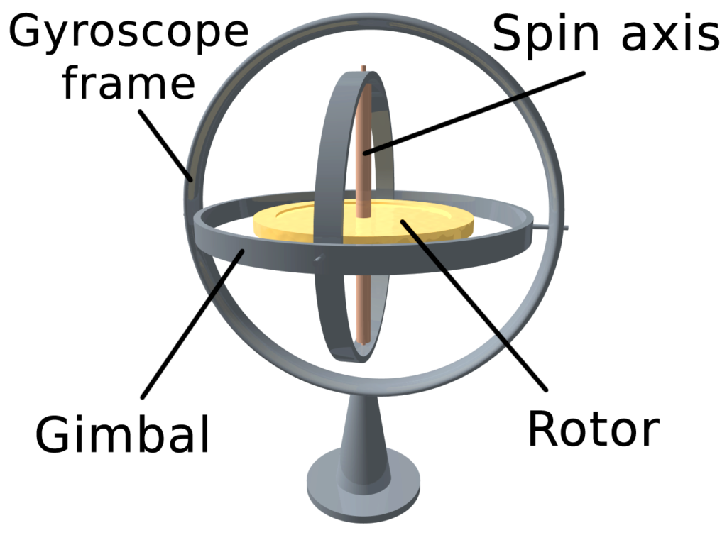
The main function of such device is to maintain orientation in respect to some reference, in general the earth. In our case the L3G4200D made by ST Semiconductors is interfaced with a ESP32-C6 via Arduino code. But it could work no problem with any Arduino, ESP8266, ESP32, Raspberry Pi Pico, etc.
The magic of our article happens due to the fact that exists an Arduino library for this gyroscope, called “L3G” from Pololu. Open your Arduino IDE, got to “Sketch > Include library > Manage libraries” and type “L3G”. Install the Pololu one.
The circuit
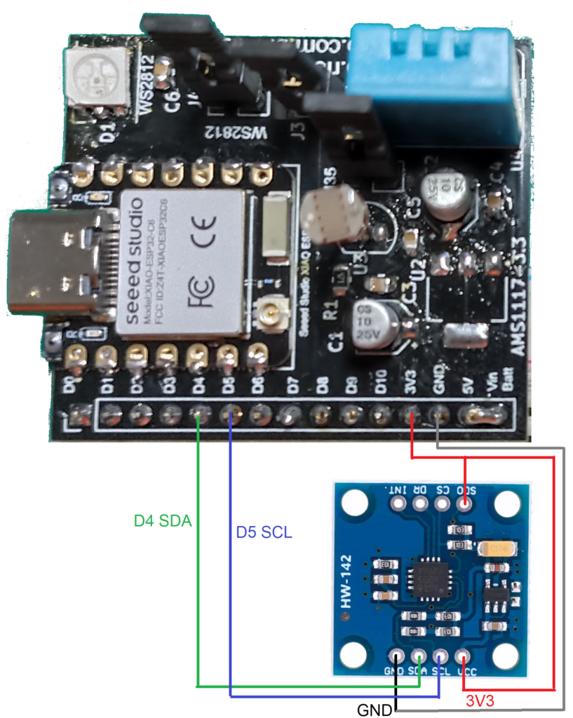
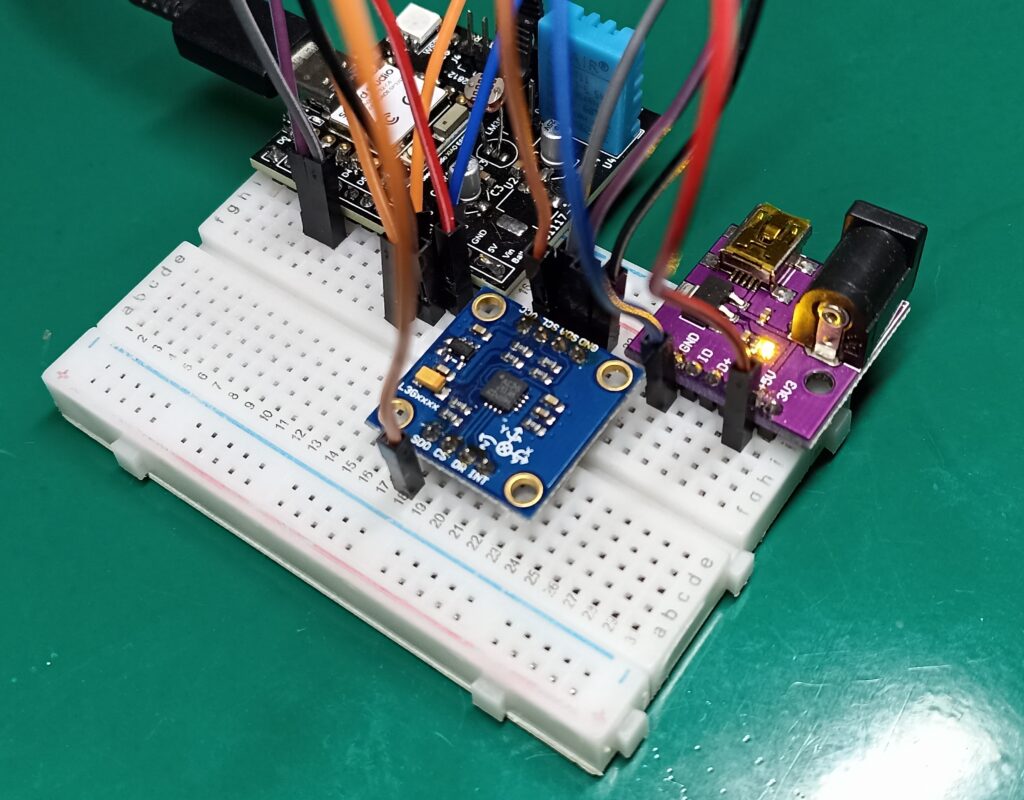
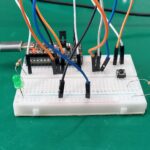
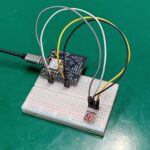
Assemble the circuit below, which besides i2c also has the SDO pin connected to 3V3. The L3G4200D module is also supplied by 3V3.
Code and testing
Now that you have installed the L3G library in your Arduino IDE and assembled the circuit, copy and paste the code below which is a simple (raw) test of the readings.
/*
The sensor outputs provided by the library are the raw 16-bit values
obtained by concatenating the 8-bit high and low gyro data registers.
They can be converted to units of dps (degrees per second) using the
conversion factors specified in the datasheet for your particular
device and full scale setting (gain).
Example: An L3GD20H gives a gyro X axis reading of 345 with its
default full scale setting of +/- 245 dps. The So specification
in the L3GD20H datasheet (page 10) states a conversion factor of 8.75
mdps/LSB (least significant bit) at this FS setting, so the raw
reading of 345 corresponds to 345 * 8.75 = 3020 mdps = 3.02 dps.
*/
#include <Wire.h>
#include <L3G.h>
L3G gyro;
void setup() {
Serial.begin(9600);
Wire.begin();
if (!gyro.init())
{
Serial.println("Failed to autodetect gyro type!");
while (1);
}
gyro.enableDefault();
}
void loop() {
gyro.read();
Serial.print("G ");
Serial.print("X: ");
Serial.print((int)gyro.g.x);
Serial.print(" Y: ");
Serial.print((int)gyro.g.y);
Serial.print(" Z: ");
Serial.println((int)gyro.g.z);
delay(100);
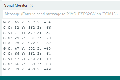
}As stated in the code body, the value being presented is not dimesional (does not have a unit). It has to be multiplied by a factor so that it represents someting in dps (degrees per second). I was not able to find such factor in the datasheet.
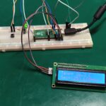
The serial monitor show something as seen below, this value changes as you spin and rotate the breadboard.
Final words
Since a gyroscope measures the rate at which the device rotates, it can be used for example for robots or quadcopters/drones. Gyrosopes are indeed part of the so-called 9-DOF (degrees o freedom) devices, allowing for precise spatial location.
If you want to buy one of these L3G4200D devices, use my affiliate link here.


Leave a Reply