Let’s learn today how to master PWM and how to use it. It stands for “Pulse width modulation” and is a technique used to “dimmerize” and control loads, be them AC or DC.
The technique consists on controlling for how long a waveform stays in HIGH and LOW level, where the average voltage value is then moved up or down accordingly to the timing. Frequency-wise the PWM is independent of it, being able to exist and function independently of frequency.
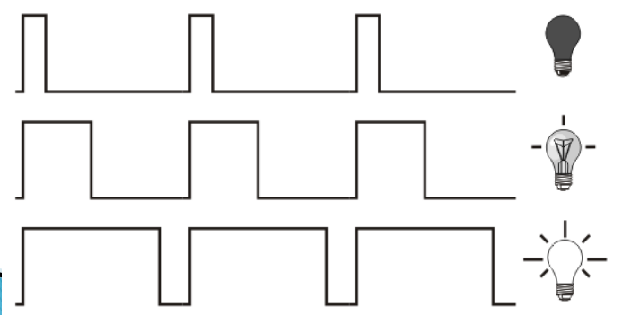
Image aboe illustrates PWM very well, showing the waveform in the left and a lightbulb in the right. The bulb lights more or less depending on the duty cycle (the time the waveform stays in HIGH level).
Usage
PWM is used wherever one wants to control the average voltage of a signal, being it AC (alternating current) or DC (direct current). A smaller duty cycle means less time in HIGH state and consequently smaller average voltage. In the other hand a higher duty cycle means more time in HIGH state and a greater average voltage.
It can even be used to recreate sinusoidal voltages, given one implements the necessary filtering and smoothing of the signal. In fact most sinusoidal solar and wind inverters used PWM as the main way of generating such sinusoid.
Arduino usage
Arduino ecossystem implements PWM control in a function called analogWrite(), taking as parameter an integer between 0 and 255. You can write (for example) analogWrite(127), which means roughly 50% duty cycle.
The Arduino IDE itself bring a ready-to-use example of PWM called “Fading”, from “File > Examples > Analog > Fading”. It is seen below.
int ledPin = D8; // LED connected to digital pin 9
void setup() {
// nothing happens in setup
}
void loop() {
// fade in from min to max in increments of 5 points:
for (int fadeValue = 0; fadeValue <= 255; fadeValue += 5) {
// sets the value (range from 0 to 255):
analogWrite(ledPin, fadeValue);
// wait for 30 milliseconds to see the dimming effect
delay(30);
}
// fade out from max to min in increments of 5 points:
for (int fadeValue = 255; fadeValue >= 0; fadeValue -= 5) {
// sets the value (range from 0 to 255):
analogWrite(ledPin, fadeValue);
// wait for 30 milliseconds to see the dimming effect
delay(30);
}
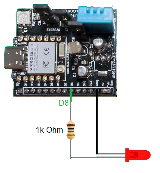
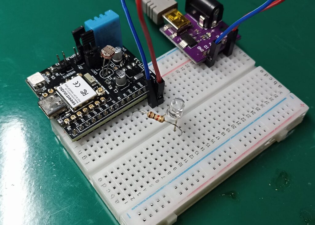
}Notice that I already changed the PWM pin “ledPin” to D8 for my ESP32-C6 dev board to work with it. The circuit and breadboard assembly is seen below.
Master PWM
Compiling and uploading the code above to the circuit shown above will result in the LED fading in and out, with PWM values between 0 and 255.
The video below shows the LED blinking/fading as intended.
Final words
Pulse width modulation is a super easy concept to grasp, yet extremely useful in the real world. Try and play with PWM yourself, see what you can do with it.


Pingback: Creating analog voltages with Arduino - FritzenLab electronics
Pingback: Control LED brightness the fancy way - FritzenLab electronics