What do you think about learning how to control a 7 segment LED display with ESP32-C6?. This is what we are doing today, using the Arduino IDE. A 7 segment LED display is a human interface device comprised of seven (actually eight) LEDs organized in a way that they show a numeric digit.
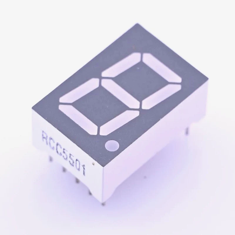
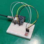
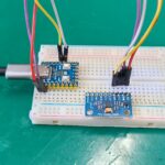
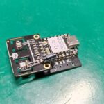
There are various sizes and colors to choose from; today we will focus on a 12x19mm one, with RED light. Besides showing numbers from 0 to 9 you can also show hexadecimal characters (A to F) and some other symbols if you want. Schematic diagram for our tests is shown below, notice that we are using my dev board based on the Xiao ESP32-C6.
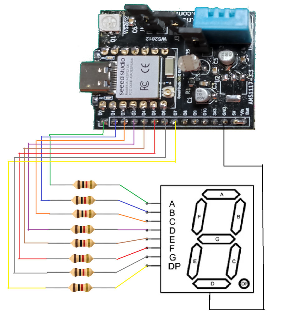
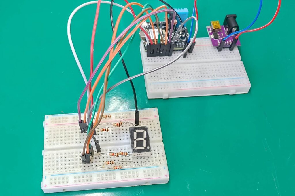
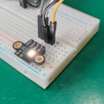
My display of choice has the configuration called common cathode, where all LEDs cathodes are connected together. I use one 1k Ohm resistor per digit, since these are “normal” LEDs and need resistors. I assembled the circuit in a breadboard configuration, seen below. It is a mess but it works, I assure you.
The code
First thing I decided to test is wether every digit works independently, or not. This is achieved with the schetch below, where I do many digitalWrite()’s in sequence to light every single digit. Also notice that I defined every output (D0..D7) as its segment name (from A to G and DP).
#define A D0
#define B D1
#define C D2
#define D D3
#define E D4
#define F D5
#define G D6
#define DP D7

void setup() {
  // put your setup code here, to run once:
  pinMode(A, OUTPUT);
  pinMode(B, OUTPUT);
  pinMode(C, OUTPUT);
  pinMode(D, OUTPUT);
  pinMode(E, OUTPUT);
  pinMode(F, OUTPUT);
  pinMode(G, OUTPUT);
  pinMode(DP, OUTPUT);

}

void loop() {
  // put your main code here, to run repeatedly:
  digitalWrite(DP, LOW);
  digitalWrite(A, HIGH);
  delay(500);
  digitalWrite(A, LOW);
  digitalWrite(B, HIGH);
  delay(500);
  digitalWrite(B, LOW);
  digitalWrite(C, HIGH);
  delay(500);
  digitalWrite(C, LOW);
  digitalWrite(D, HIGH);
  delay(500);
  digitalWrite(D, LOW);
  digitalWrite(E, HIGH);
  delay(500);
  digitalWrite(E, LOW);
  digitalWrite(F, HIGH);
  delay(500);
  digitalWrite(F, LOW);
  digitalWrite(G, HIGH);
  delay(500);
  digitalWrite(G, LOW);
  digitalWrite(DP, HIGH);
  delay(500);

}
Uploading the code and running it on the ESP32-C6 resulted in the video below. Notice I used 500ms delays, so that every segment is shown for half a second.
Showing numbers and letters
Now that we know every segment to be working, it is time to implement a slightly more complex code. We are going to show numbers from 1 to 9 and 0, and then letters from A to F. For that I have created functions, so that every “digit” is incapsulated within its own realm.
I also had to create a clear() function to be called every time a digit changes, so that I don’t have to turn off digits individually every time. This way I avoid forgetting to clear digits, automating it. Make use you select the Xiao ESP32-C6 board on the Arduino IDE; hit upload and let’s see the result.
#define A D0
#define B D1
#define C D2
#define D D3
#define E D4
#define F D5
#define G D6
#define DP D7

void clear(){
  digitalWrite(A, LOW);
  digitalWrite(B, LOW);
  digitalWrite(C, LOW);
  digitalWrite(D, LOW);
  digitalWrite(E, LOW);
  digitalWrite(F, LOW);
  digitalWrite(G, LOW);
  digitalWrite(DP, LOW);

}
void one(){
  digitalWrite(B, HIGH);
  digitalWrite(C, HIGH);
}
void two(){
  digitalWrite(A, HIGH);
  digitalWrite(B, HIGH);
  digitalWrite(D, HIGH);
  digitalWrite(E, HIGH);
  digitalWrite(G, HIGH);
}
void three(){
  digitalWrite(A, HIGH);
  digitalWrite(B, HIGH);
  digitalWrite(C, HIGH);
  digitalWrite(D, HIGH);
  digitalWrite(G, HIGH);
}
void four(){
  digitalWrite(B, HIGH);
  digitalWrite(C, HIGH);
  digitalWrite(F, HIGH);
  digitalWrite(G, HIGH);
}
void five(){
  digitalWrite(A, HIGH);
  digitalWrite(C, HIGH);
  digitalWrite(D, HIGH);
  digitalWrite(F, HIGH);
  digitalWrite(G, HIGH);
}
void six(){
  digitalWrite(A, HIGH);
  digitalWrite(C, HIGH);
  digitalWrite(D, HIGH);
  digitalWrite(E, HIGH);
  digitalWrite(F, HIGH);
  digitalWrite(G, HIGH);
}
void seven(){
  digitalWrite(A, HIGH);
  digitalWrite(B, HIGH);
  digitalWrite(C, HIGH);
}
void eight(){
  digitalWrite(A, HIGH);
  digitalWrite(B, HIGH);
  digitalWrite(C, HIGH);
  digitalWrite(D, HIGH);
  digitalWrite(E, HIGH);
  digitalWrite(F, HIGH);
  digitalWrite(G, HIGH);
}
void nine(){
  digitalWrite(A, HIGH);
  digitalWrite(B, HIGH);
  digitalWrite(C, HIGH);
  digitalWrite(F, HIGH);
  digitalWrite(G, HIGH);
}
void zero(){
  digitalWrite(A, HIGH);
  digitalWrite(B, HIGH);
  digitalWrite(C, HIGH);
  digitalWrite(D, HIGH);
  digitalWrite(E, HIGH);
  digitalWrite(F, HIGH);
}
void a(){
  digitalWrite(A, HIGH);
  digitalWrite(B, HIGH);
  digitalWrite(C, HIGH);
  digitalWrite(E, HIGH);
  digitalWrite(F, HIGH);
  digitalWrite(G, HIGH);
}
void b(){
  digitalWrite(C, HIGH);
  digitalWrite(D, HIGH);
  digitalWrite(E, HIGH);
  digitalWrite(F, HIGH);
  digitalWrite(G, HIGH);
}
void c(){
  digitalWrite(A, HIGH);
  digitalWrite(D, HIGH);
  digitalWrite(E, HIGH);
  digitalWrite(F, HIGH);
}
void d(){
  digitalWrite(B, HIGH);
  digitalWrite(C, HIGH);
  digitalWrite(D, HIGH);
  digitalWrite(E, HIGH);
  digitalWrite(G, HIGH);
}
void e(){
  digitalWrite(A, HIGH);
  digitalWrite(D, HIGH);
  digitalWrite(E, HIGH);
  digitalWrite(F, HIGH);
  digitalWrite(G, HIGH);
}
void f(){
  digitalWrite(A, HIGH);
  digitalWrite(E, HIGH);
  digitalWrite(F, HIGH);
  digitalWrite(G, HIGH);
}
void setup() {
  // put your setup code here, to run once:
  pinMode(A, OUTPUT);
  pinMode(B, OUTPUT);
  pinMode(C, OUTPUT);
  pinMode(D, OUTPUT);
  pinMode(E, OUTPUT);
  pinMode(F, OUTPUT);
  pinMode(G, OUTPUT);
  pinMode(DP, OUTPUT);

}

void loop() {
  // put your main code here, to run repeatedly:
  one();
  delay(500);
  clear();
  two();
  delay(500);
  clear();
  three();
  delay(500);
  clear();
  four();
  delay(500);
  clear();
  five();
  delay(500);
  clear();
  six();
  delay(500);
  clear();
  seven();
  delay(500);
  clear();
  eight();
  delay(500);
  clear();
  nine();
  delay(500);
  clear();
  zero();
  delay(500);
  clear();
  a();
  delay(500);
  clear();
  b();
  delay(500);
  clear();
  c();
  delay(500);
  clear();
  d();
  delay(500);
  clear();
  e();
  delay(500);
  clear();
  f();
  delay(500);
  clear();
}
As you are going to see in the video below, every number and hexadecimal digit is shown alternating every 500ms (half a second).
Final words
Controlling 7 segments LED displays is a well known and dominated “science”; it is a matter of coordinating which output to turn ON or OFF. Same as controlling one digit is to control more (say four for example), one just needs to use four more microcontroller pins.
Want to know more about displays? check this round display control out. Want to buy some display for experiments? use my affiliate link.

Leave a Reply