Let’s get to know the SDB628 boost circuit board. That is an integrated circuit made into a module called HW-668 (or SX-1308). Based on the SDB628 chip, you can find the datasheet here. If you want to buy this circuit board, click here.
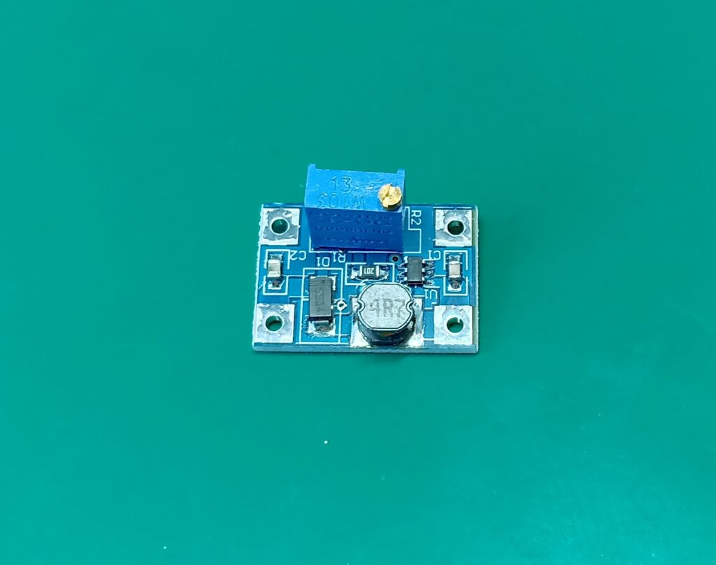
Boost or step up means that its output voltage is higher than the input voltage. In the case of this chip, the input voltage is between 2 and 24V, with variable output up to 28V at 4A (theoretical limit not tested, according to the datasheet).
A typical application circuit for this boost converter is found in the image below, from this datasheet. You will notice a couple of things:
- Every boost circuit (as well as bucks) feature at least one inductor and one power diode.
- There may be (in this case there is) a voltage feedback circuit, via R1 and R2.
- There is a one pin for enable/disable. It serves to stop the circuit functionality.
- There are always recommended capacitors both in the input and output.
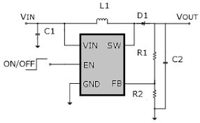
Such inductor is one fo the most important parts of any boost circuit. It basically stores energy during part of the cycle then releases it in the other part. This effectively raises the output voltage over the input one. Inductor size generally depends on two things: current and switching frequency. Since SDB628 oscillates at 1.2MHz, the inductor size can be made pretty small.
The power diode makes it impossible for energy to go back to the source. It also does double functions depending on the moment. During part of the cyle it conducts energy from input to output, during the other part it blocks such energy from coming back.
The feedback circuit is not really mandatory, but most chips implement in for energy quality and tight marketeable specs. Some industries and applications can not simply see their boost converter circuit fail or be outside certain limits.
The test setup
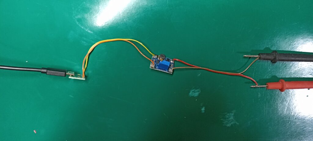
I started my tests by making a cable to convert from USB to wires, as shown in the image below (green board and yellow and orange cables). The USB cable was connected to one of these cell phone chargers, the input voltage is therefore 5V. A multimeter on the voltage scale was used to measure the converter output.
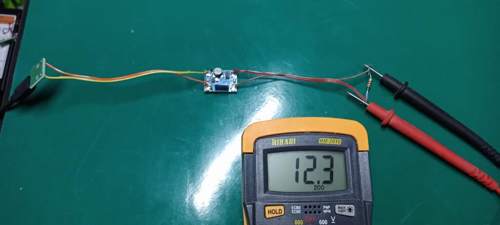
Initially I placed a 1k Ohm resistor as a load at 12.3V, just a few milliamps. I didn’t hear any switching noise nor did I notice the converter heating up. The noise really is not there due to the high enough switching frequency, which is 1.2MHz.
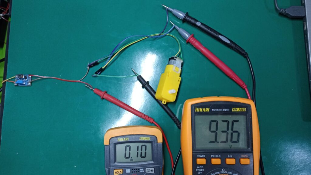
Then I tested it with a DC motor at 9.3V, the current was on average 100-120mA and the voltage remained constant. That was the most current I could take out of this chip, the heaviest load I had at hand. I also did not observe any audible switching noise or heating.
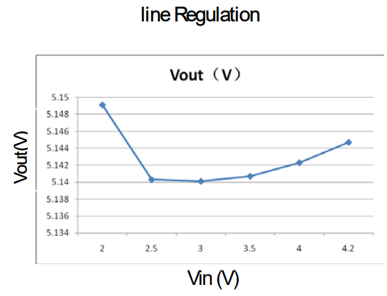
Line regulation is really not a problem for this chip, just look at the graph below, from its datasheet. Of course that is just one point of measurement, but judging by its feedback circuit it regulates pretty well.
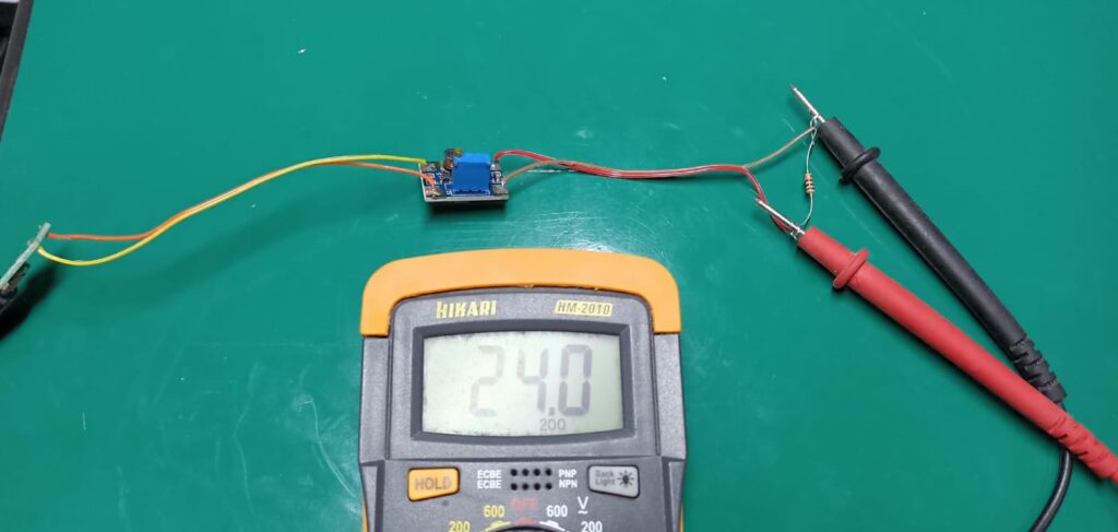
Finally I raised the voltage to 24V from 5V, again placing a 1k Ohm resistor as a load. Current in this case was only 24 mA, enough to prove a point. What is still pending for me to do is test this chip under load, to see up to which current it keeps its reguation.
I did not observe any audible noise or heating of the converter. That was one of the coolest parts of testing this integrated circuit, its switching frequency. It is not so common to see such a high switching frequency, specially due to printed circuit board layout. Also due to higher energy losses in semiconductors and passives. But that is what the manufacturer os this chip did, and did well.
Final words
The SDB628 step up/boost converter was able to increase the voltage from 5V of the USB port to 9V, 12V and 24V. I tested it with current up to 120mA, but according to the datasheet it supports much more. This high current test is still pending, will bring it to you when the opportunity arises.
Most hobbists will not come to a point where they need to use a boost circuit, let alone calculate one. My article brings a bit of clarity to those people, I have tested SDB628 boost so they do not have to.
If you want to buy this boost/step up module, click here. If you want to learn more about the basics of electronics, check out this article about the PIR presence sensor.


